Smart watch and control method for the same

Active Publication Date: 2014-10-07
LG ELECTRONICS INC
View PDF16 Cites 106 Cited by
  • Summary
  • Abstract
  • Description
  • Claims
  • Application Information

AI Technical Summary

Benefits of technology

[0008]In one embodiment, an object of the disclosure is to provide a smart watch which provides a notification indicating at least one event that is scheduled to occur after detecting a take-off signal, if the smart watch detects a take-off signal, thereby assisting a user in predicting an up-coming event even in a state in which the smart watch is taken off.

Problems solved by technology

Smart-phones or tablet PCs may be inconvenient because the user has to put a smart-phone or tablet PC in a pocket or bag or to hold the same, although the user may easily manipulate the smart-phone

Method used


Image

  • Smart watch and control method for the same
  • Smart watch and control method for the same
  • Smart watch and control method for the same

Examples


first embodiment

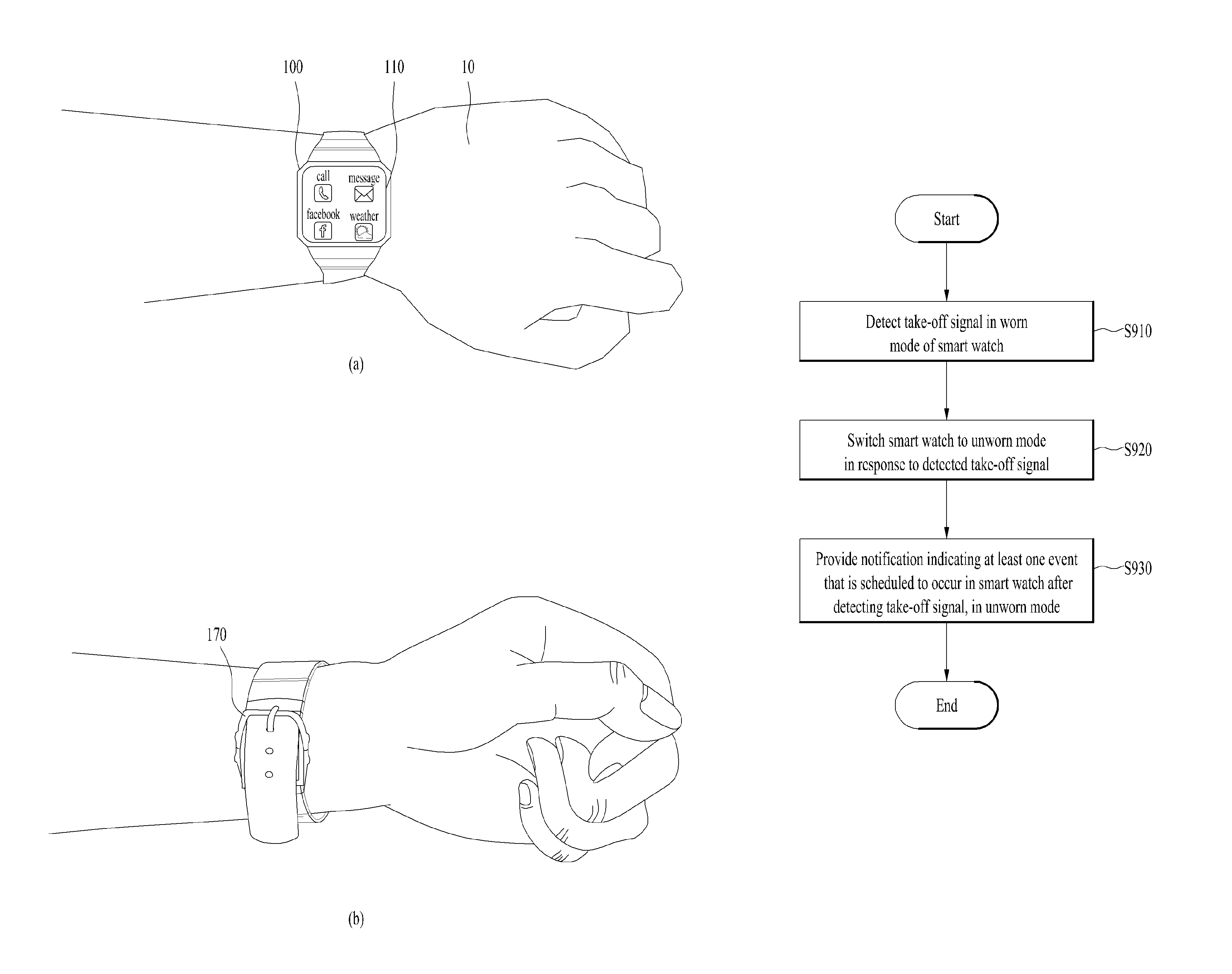
[0047]FIG. 4 is a view showing a control method for the smart watch according to the disclosure. More specifically, FIG. 4 shows provision of a notification in the case in which the smart watch 100 is switched from a worn mode (t0) to an unworn mode (t1).

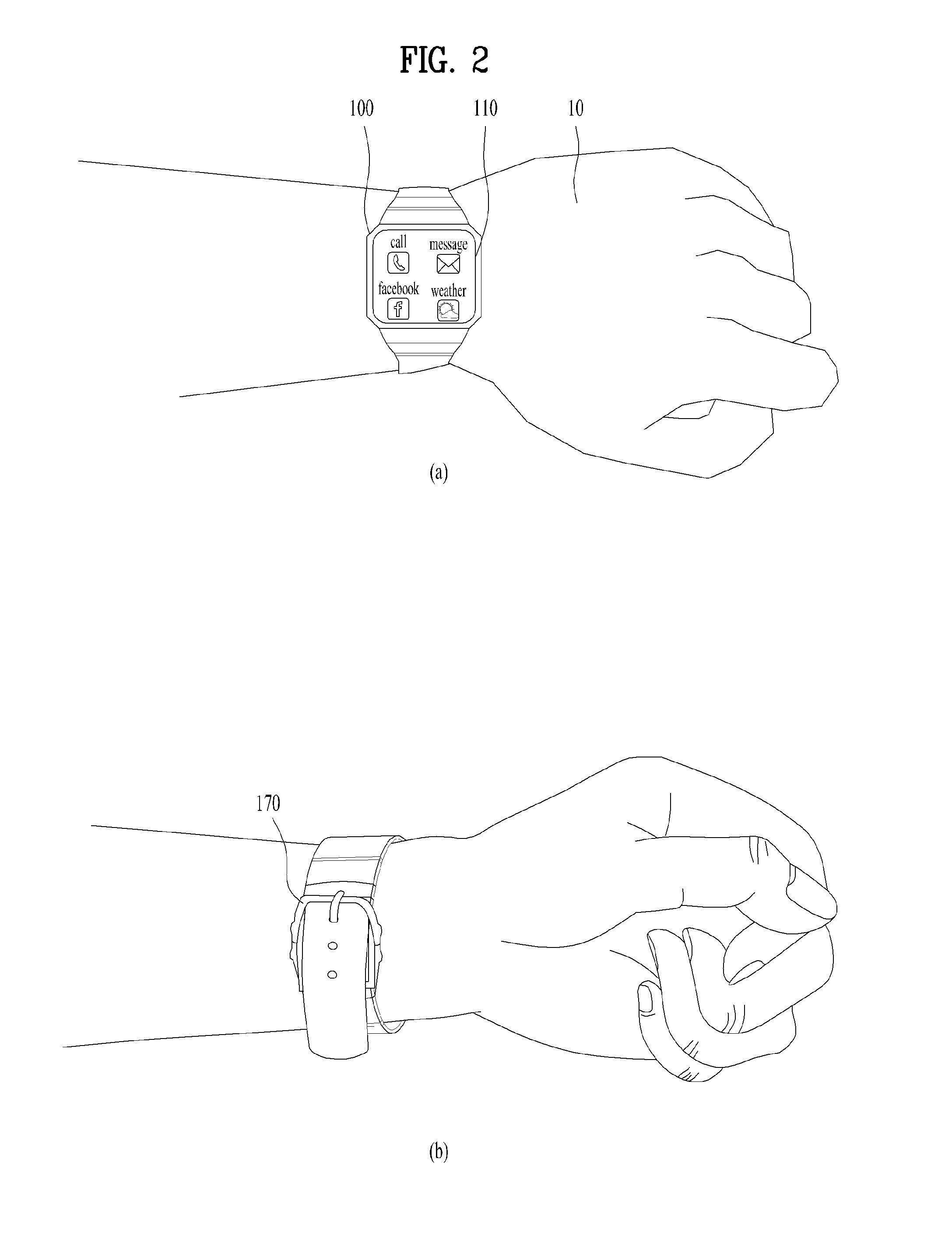
[0048]First, a time t0 corresponds to a worn mode, i.e. a state in which the smart watch 100 is worn by the user 10. As described above with reference to FIG. 2, whether or not the smart watch 100 is worn may be determined based on the input signal with regard to at least one of the rear surface (not shown) of the smart watch 100 and the buckle (not shown) of the smart watch 100. In addition, at the time t0, the smart watch 100 may display a home screen or content that is in use from before. For example, as exemplarily shown in FIG. 4, at the time t0, the smart watch 100 displays a home screen, on which letters as well as icons, such as telephone symbols, etc., are displayed.

[0049]Next, at a time t1, the smart watch 100 may detect a...

second embodiment

[0055]FIG. 5 is a view showing a control method for the smart watch according to the disclosure. More specifically, FIG. 5 shows whether or not to unpair between the smart watch 100 and the external digital device 200 if the smart watch 100 is switched from a worn mode to an unworn mode.

[0056]First, in a worn mode of the smart watch 100, the smart watch 100 may perform pairing with the external digital device 200. As described above with reference to FIG. 3, once pairing is completed, the smart watch 100 may transmit or receive data via communication with the external digital device 200. Next, the smart watch 100 may detect a take-off signal. Next, the smart watch 100 may be switched to an unworn mode in response to the detected take-off signal.

[0057]In this case, the smart watch 100 may display a pairing interface 20 on the display unit. The pairing interface 20 is used to set whether or not to unpair between the smart watch 100 and the external digital device 200. In one embodimen...

third embodiment

[0059]FIG. 6 is a view showing a control method for the smart watch according to the disclosure. More specifically, FIG. 6 shows power on / off of the smart watch 100 when the smart watch 100 is switched from a worn mode to an unworn mode.

[0060]First, as described above with reference to FIGS. 4 and 5, the smart watch 100 may detect a take-off signal in a worn mode thereof. Next, the smart watch 100 may be switched to an unworn mode in response to the detected take-off signal. In this case, the smart watch 100 may display a power on / off interface 40 on the display unit 110. The power on / off interface 40 is used to set whether or not to turn on or off the smart watch 100. In one embodiment, the smart watch 100 may be turned off upon detecting a power-off input signal with regard to the smart watch 100. In this case, the display unit 110 of the smart watch 100 may be deactivated. That is, no content may be displayed on the display unit 110 of the smart watch 100. Additionally, in this c...


PUM


Abstract

Discussed are a smart watch and a control method for the same, which provide a notification indicating events, which are scheduled to occur later on the basis of a take-off time, if the smart watch is taken off. The smart watch includes a display unit to display content, a communication unit to perform transmission/reception of data, and a sensor unit to detect an input signal with regard to the smart watch and transmit the signal to a processor that serves to control the aforementioned units. The processor detects a take-off signal, indicating separation of the smart watch from a user, in a worn mode, to switch the smart watch to an unworn mode in response to the detected take-off signal, and provides a notification indicating at least one event that is scheduled to occur after detecting the take-off signal in the unworn mode.

Description

[0001]Pursuant to 35 U.S.C. §119(a), this application claims the benefit of Korean Patent Application No. 10-2013-0044001, filed on Apr. 22, 2013, which is hereby incorporated by reference as if fully set forth herein.BACKGROUND OF THE INVENTION[0002]1. Field of the Invention[0003]The disclosure relates to a smart watch and a control method for the same, and more particularly to a method to provide a notification indicating events, which are scheduled to occur in the smart watch after detecting the take-off signal, if a smart watch is taken off.[0004]2. Discussion of the Related Art[0005]Development of wearable computers is accelerating with advances in technologies. Here, wearable computers refer to computers that a user can naturally wear, like clothes, watches, glasses, and accessories. Smart-phones or tablet PCs may be inconvenient because the user has to put a smart-phone or tablet PC in a pocket or bag or to hold the same, although the user may easily manipulate the smart-phon...

Claims


Application Information

Patent Timeline
IPC IPC(8): G04B47/00A44C5/00H04M1/00G04G9/00H04M1/72412H04M1/72454
CPCG04G9/0005H04M1/21H04M7/0033G04G21/00G04G9/0064G04G21/04G04G19/12G06F1/163G06F1/3206H04M1/7253G04G21/08G06F1/3265Y02B60/1242Y02D10/00H04M1/72412G06F3/01G06F3/014G06F3/14G06F13/14
Inventor LEE, DOYOUNGKIM, YONGSINPARK, HYORIM
Owner LG ELECTRONICS INC
Why Eureka
Try Eureka