Method for operating a radar system

a radar system and radar system technology, applied in the field of radar system operation, can solve the problems of high cost, high cost, and complex solution for adequate transmission-reception decoupling, and achieve the effects of avoiding the disadvantages of pulse radar system operation and fmcw radar system, low cost, and high resolution

Inactive Publication Date: 2000-11-14
AUTOMOTIVE DISTANCE CONTROL SYST
View PDF6 Cites 83 Cited by
  • Summary
  • Abstract
  • Description
  • Claims
  • Application Information

AI Technical Summary

Benefits of technology

The object of the invention is to provide a method for operating a radar system in which the disadvantages associated with the operation of a pulse radar system and a FMCW radar system are avo

Problems solved by technology

The complexity of the pulse radar system and the associated high costs are disadvantageous because on the one hand the distance resolution depends solely on the pulse-on time and therefore with the very short pulse-on times needed to realize a high distance resolution (e.g., 1 m) a very fast signal processing of the received signal is also necessary (e.g., by digitally sampling the received signal by means of analog-to-digital converters with high clock frequency), and because on the other hand the signal processing of the received signal is very elaborate and furthermore is determined by the bandwidth of the transmission signal.

Method used


Image

  • Method for operating a radar system
  • Method for operating a radar system
  • Method for operating a radar system

Examples


Embodiment Construction

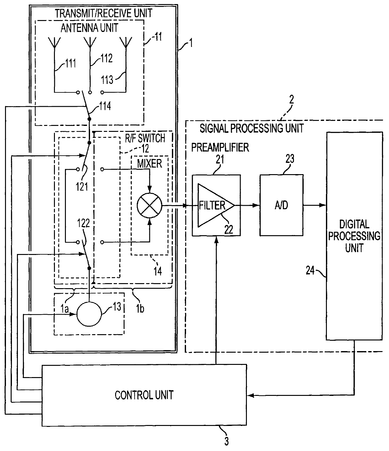
The method for operating a radar system will now be described in more detail with reference to a distance sensor for a motor vehicle distance warning system.

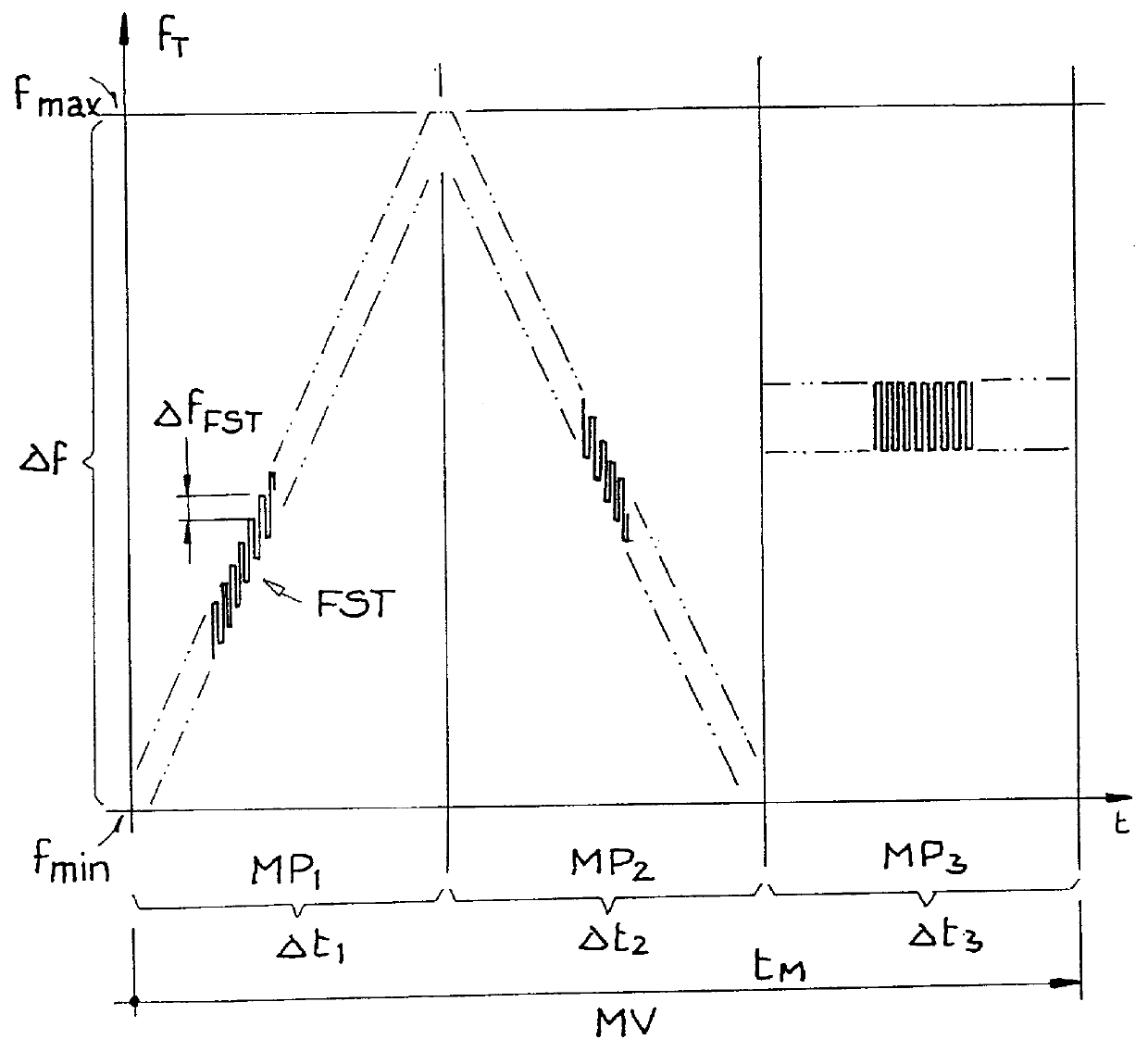
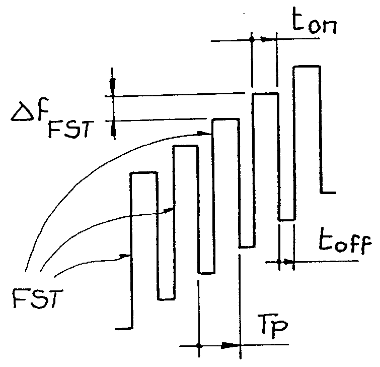
Distance sensors in motor vehicle distance warning systems are required to determine distinctly and with high resolution the distance (and possibly the relative velocity) of at least one target object, i.e., of vehicles, persons and other reflection objects travelling ahead, approaching from the opposite direction or following from behind, as a rule of all target objects situated in the observation range at one and the same time. For example, the desired distance distinctness range is 150 m (this is relatively short compared with other radar systems), the desired distance resolution 1 m, and the desired velocity resolution 1 m / s. In at least one measuring phase of the measurement process a transmission signal is emitted from the (transmission) antenna of the "pulse FMCW radar system" with a transmission frequency of, for instanc...


PUM


Abstract

In a method for operating a radar system, the object is to determine by simple means and at low cost the distance and/or the radial velocity of at least one target object with high resolution. For this purpose, in each measuring phase of the measurement process in the "pulse FMCW radar system", switchover between a transmission mode and a receiving mode is effected a multiple number of times and at short intervals of time. In the transmission mode, all receiving units of the radar system are switched off, while a pulse-shaped (frequency-modulated) transmission signal with time-successive transmission pulses having a specific pulse-on time and a specific carrier frequency is emitted from at least one transmitter unit of the radar system. In receiving mode, all transmitter units are switched off in the pulse-off times of the transmission pulses, while from at least one receiver unit all reflection signals originating from the last emitted transmission pulse are detected as received signal from the entire observation range before emission of the next transmission pulse. The distance and/or the radial velocity of the reflection objects is determined indirectly by the signal processing unit of the radar system by evaluation of the frequency difference and/or phase difference between the transmission signal and the received signal.

Description

Radar systems are used to determine the distance to moving or stationary objects (target objects) and / or to determine the (relative) velocity of moving or stationary objects (target objects) in different observation ranges (distance ranges). The main areas of application for radar systems are as a rule observation ranges with long distances between the radar and the target object(s) ("long-distance range", e.g., a distance of up to 150 km or 300 km depending on the application), for instance in aviation for flight safety or for navigation purposes. More recently, there are also applications for radar systems in observation ranges with a very short distance between radar and target object(s) ("close range", e.g. up to 20 m or 250 m depending on the application), for instance in motor vehicle applications for determining the distance to motor vehicles travelling in front or behind, or approaching from another direction, or to other reflection objects, and / or the relative velocity of m...

Claims


Application Information

Patent Timeline
IPC IPC(8): G01S13/00G01S13/58G01S13/28G01S13/34G01S13/24G01S13/93G01S13/32G01S7/02G01S7/28G01S13/931
CPCG01S13/28G01S13/58G01S13/24G01S13/931G01S13/345G01S13/32
Inventor ROHLING, HERMANNMENDE, RALPH
Owner AUTOMOTIVE DISTANCE CONTROL SYST
Why Eureka
Try Eureka