Ultrasound vibrometry

a vibrometry and ultrasonic technology, applied in the field of coherent imaging, can solve the problem that the optical method of measuring the very small harmonic motion of the subject tissue cannot be used, and achieve the effect of improving the accuracy of the measurement results

Active Publication Date: 2010-07-13
MAYO FOUND FOR MEDICAL EDUCATION & RES
View PDF18 Cites 79 Cited by
  • Summary
  • Abstract
  • Description
  • Claims
  • Application Information

AI Technical Summary

Problems solved by technology

Where the subject tissue is buried deeply beneath other tissue, optical methods for measuring the very small harmonic motions of the subject tissue cannot be used.
The challenge is to extract this information from the echo signals where the amplitude of the harmonic motion is at the submicron level.

Method used


Image

  • Ultrasound vibrometry
  • Ultrasound vibrometry
  • Ultrasound vibrometry

Examples


Embodiment Construction

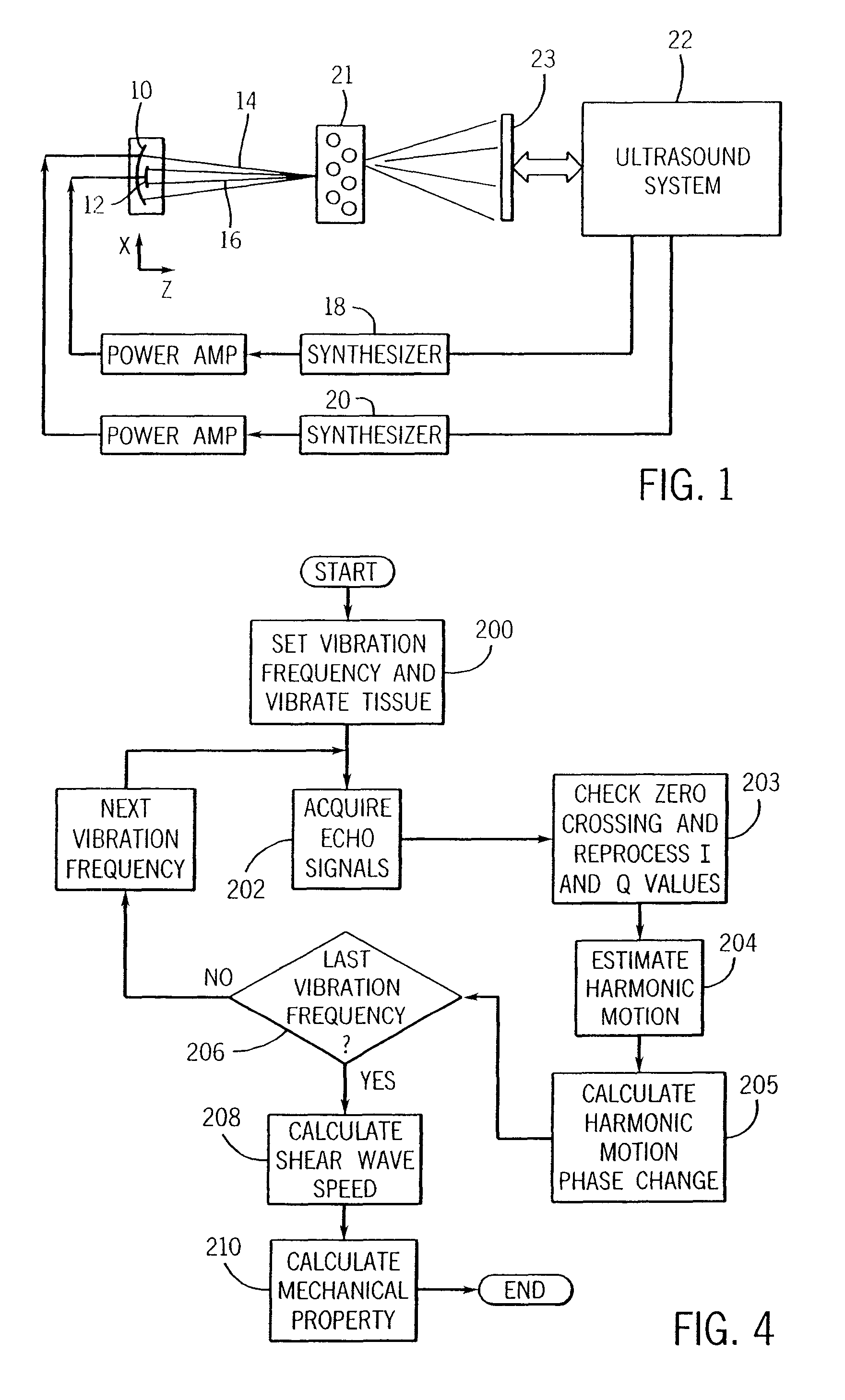
[0058]Referring particularly to FIG. 1, a vibro-acoustography system which employs the present invention employs an ultrasonic transducer having two elements 10 and 12 which produce two focused beams 14 and 16 that cross each other at their focal points as described in U.S. Pat. No. 5,991,239. The elements 10 and 12 are driven by respective continuous wave synthesizers 18 and 20 at ultrasonic frequencies ω1 and ω2 that differ by a desired beat frequency. The two focused beams 14 and 16 are aimed at target tissue 21 which is to be measured, and in response, the target tissue vibrates, or oscillates, at the difference frequency. These elements thus serve as a force generator which oscillates the target tissues 21 at a prescribed beat frequency.

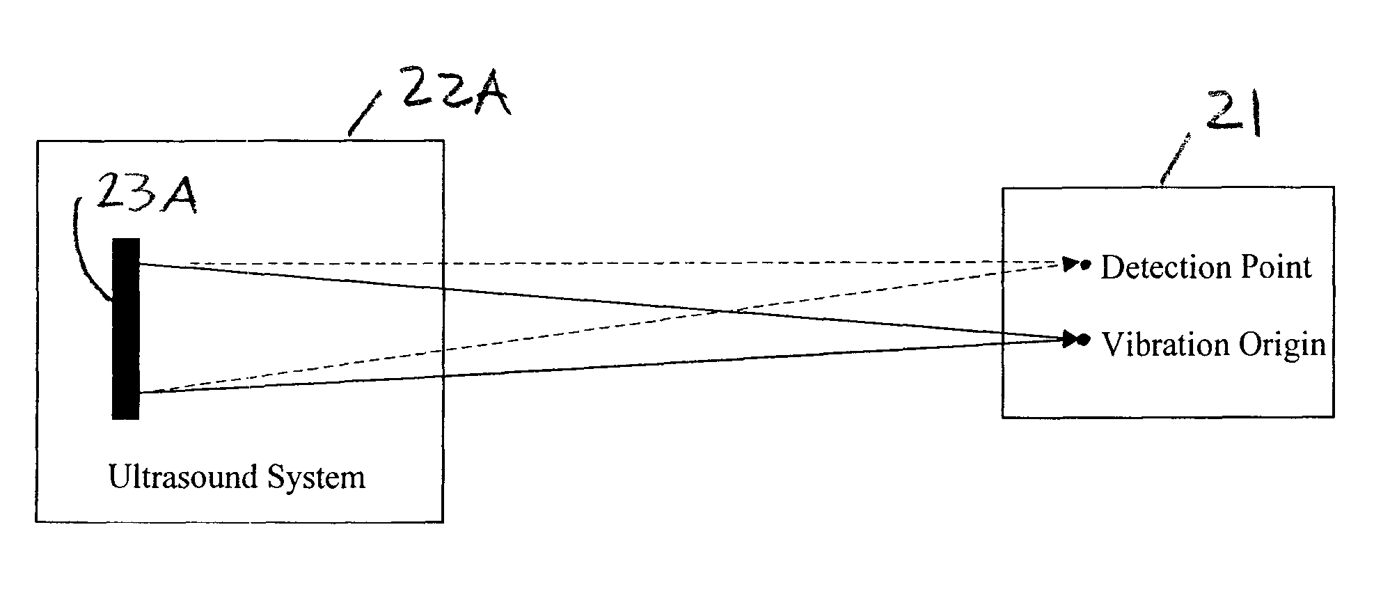
[0059]The vibrations of the target tissue 21 are measured by an ultrasound system 22. As will be described in more detail below, the ultrasound system 22 drives an ultrasonic transducer 23 to apply a focused ultrasound beam to the target tissue ...


PUM


Abstract

A method for measuring a mechanical property of a subject includes using an ultrasonic transducer to apply ultrasonic vibration pulses to a vibration origin in the subject in an on-off time sequence in order to impart a harmonic motion at a prescribed frequency to the subject, and when the vibration pulses are off, using the same transducer to apply ultrasonic detection pulses to a motion detection point and to receive echo signals therefrom in order to sense the harmonic motion on the subject at the motion detection point. From the harmonic signal information, a harmonic signal is detected and a characteristic such as amplitude or phase of the detected harmonic signal is measured. The mechanical property is calculated using the measured characteristic using for example a wave speed dispersion method.

Description

CROSS-REFERENCE TO RELATED APPLICATIONS[0001]This application is a continuation-in-part application of and claims the benefit of U.S. patent application Ser. No. 10 / 956,461 filed on Oct. 1, 2004 and entitled “Detection of Motion in Vibro-Acoustography”, which claims the benefit of U.S. Provisional patent application Ser. No. 60 / 508,371 filed on Oct. 3, 2003 and entitled “Motion Detection for Vibroacoustography”; and claims the benefit of U.S. patent application Ser. No. 10 / 821,461 filed on Apr. 9, 2004 and entitled “Method and Apparatus For Shear Property Characterization From Resonance Induced by the Oscillatory Radiation Force”, which claims the benefit of U.S. Provisional patent application Ser. No. 60 / 461,605 filed on Apr. 9, 2003 and entitled “Method and Apparatus For Shear Property Characterization From Resonance Induced by the Oscillatory Radiation Force”.STATEMENT REGARDING FEDERALLY SPONSORED RESEARCH OR DEVELOPMENT[0002]This invention was made with government support under...

Claims


Application Information

Patent Timeline
Patent Type & Authority Patents(United States)
IPC IPC(8): A61B8/00
CPCA61B5/0048A61B8/485A61B8/00A61B5/0051
Inventor GREENLEAF, JAMES FOWLERCHEN, SHIGAOZHENG, YI
Owner MAYO FOUND FOR MEDICAL EDUCATION & RES
Why Eureka
Try Eureka