

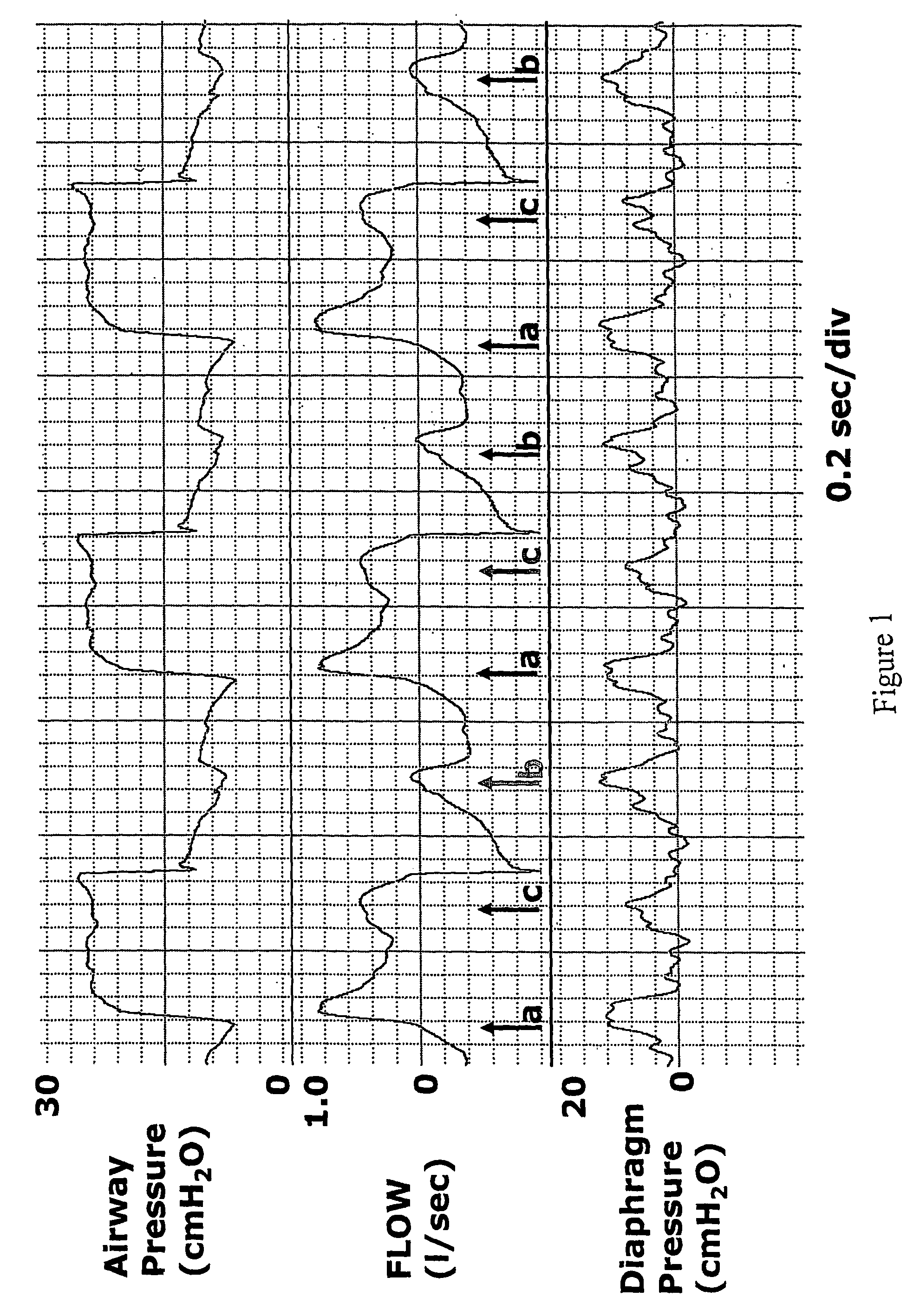
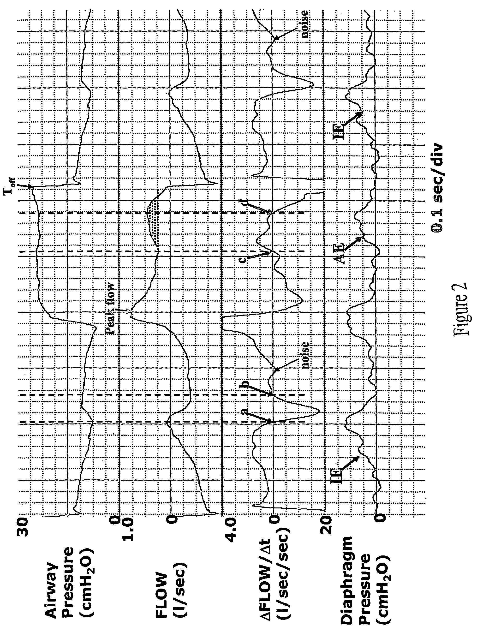
Synchrony between end of ventilator cycles and end of patient efforts during assisted ventilation
a technology of assisted ventilation and which is applied in the field of synchrony between end and end, can solve the problems of many patient cycle ineffective triggering of ventilator cycle, excessive sedation and sleep disruption, and no mechanism to ensure the end of ventilator cycl
- Summary
- Abstract
- Description
- Claims
- Application Information
AI Technical Summary
Benefits of technology
Problems solved by technology
Method used
Image

Examples
Embodiment Construction
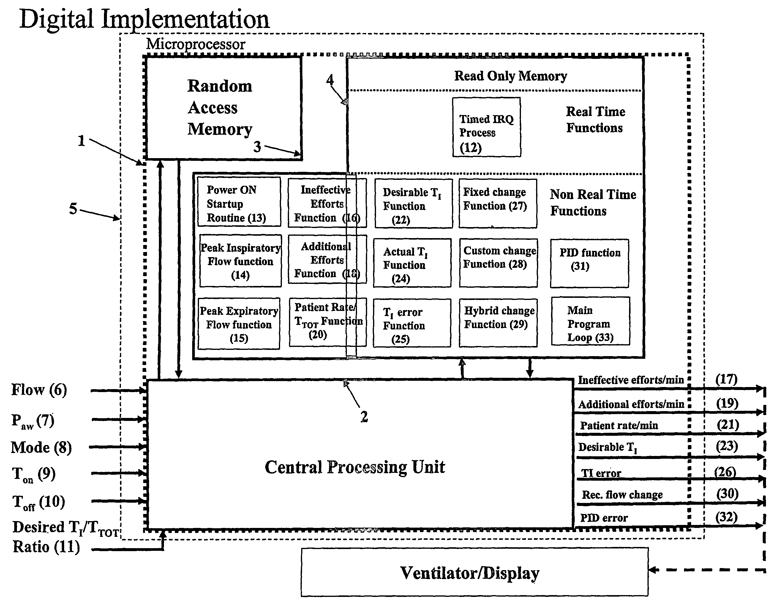
[0018]A digital implementation of a preferred embodiment of the invention will be described here (FIG. 3) because the method of the invention is primarily intended for incorporation in microprocessor-based ventilators. As such, the method can be installed in a free-standing microprocessor that interacts with the ventilator's control circuitry or may be fully incorporated in the ventilator's resident computer. It is recognized, however, that most of the functions described here can be implemented using standard analog circuits.
[0019]The basic hardware requirements (microprocessor, 1) are a Central Processing Unit (CPU, 2), Random Access Memory (RAM, 3) and Read Only Memory (ROM, (4)).
[0020]A. Inputs:
[0021]It is assumed here that inputs are in digital form. If some or all are available only in analog form, an analog to digital converter (not shown) must be installed upstream from the CPU to receive and digitize the analog inputs.
[0022]Inputs may vary depending on user preference and i...
PUM
 Abstract
Description
Claims
Application Information