
Radar, lidar and camera enhanced methods for vehicle dynamics estimation

a vehicle dynamics and camera technology, applied in the field of vehicle dynamics estimation system and method, can solve the problems of reducing the performance of wheel speed sensors during wheel slippage, increasing errors in position and velocity, and current automotive-grade mems imus alone being typically not suitable for dead-reckoning

Active Publication Date: 2014-10-07
GM GLOBAL TECH OPERATIONS LLC
View PDF21 Cites 21 Cited by
  • Summary
  • Abstract
  • Description
  • Claims
  • Application Information

AI Technical Summary

Benefits of technology

This system enhances the accuracy and reliability of vehicle dynamics estimation by leveraging object sensors and in-vehicle sensors, reducing errors and maintaining performance even in challenging conditions like wheel slippage and urban canyons, thereby supporting advanced driver assist systems.

Problems solved by technology

However, the performance of wheel speed sensors is reduced during wheel slippage conditions, such as when the driver performs cornering and swerving maneuvers.
Because MEMS IMUs usually have larger errors than expensive gyro-systems, errors in position and velocity can grow rapidly.
Thus, current automotive-grade MEMS IMUs alone are typically not suitable for dead-reckoning for a long period of time.
However, few of these systems address the issue that the GPS signals are not always available, such as when the vehicle is in “urban canyons” where an insufficient number of satellites are tracked to determine the position and the velocity of the vehicle.
However, none of these approaches alone is reliable enough in cluttered scenes.
Further, few of these systems make explicit the essential need for system integration that will be necessary in the future commercial development of this technology.

Method used


Image

  • Radar, lidar and camera enhanced methods for vehicle dynamics estimation
  • Radar, lidar and camera enhanced methods for vehicle dynamics estimation
  • Radar, lidar and camera enhanced methods for vehicle dynamics estimation

Examples


Embodiment Construction

[0014]The following discussion of the embodiments of the invention directed to a system and method for estimating vehicle dynamics using radar, lidar and / or camera signals is merely exemplary in nature, and is in no way intended to limit the invention or its applications or uses.

[0015]As will be discussed in detail below, the present invention proposes an integrated system using low-cost MEMS IMUs and other in-vehicle dynamic sensors to correct vehicle dynamics estimations in real-time using supporting sensors, such as radar, lidar, vision systems or combinations thereof. This will allow either improved performance from existing sensors or the same performance from smaller and cheaper sensors.

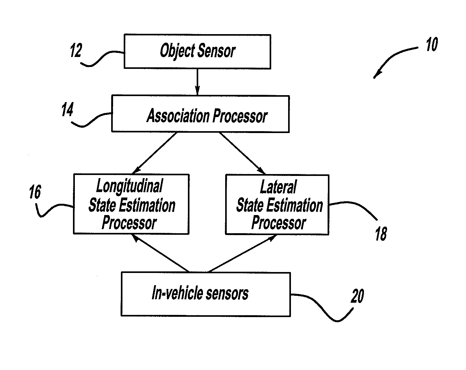
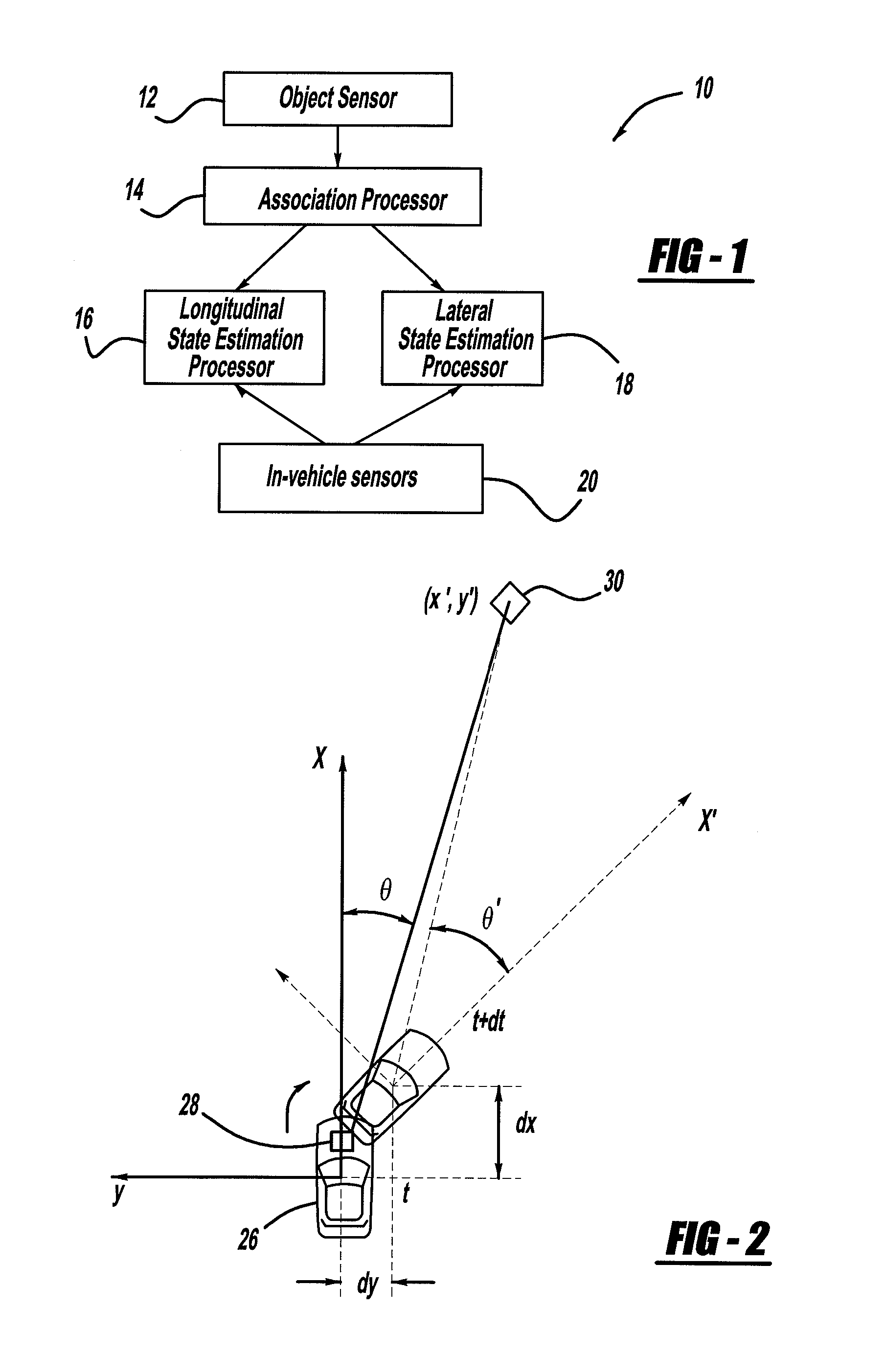
[0016]FIG. 1 is a block diagram of a system 10 that provides vehicle state estimations, such as vehicle position and velocity, according to an embodiment of the present invention. The system 10 includes one or more object sensors 12, such as radar, lidar, vision systems, cameras, etc., that may...


PUM


Abstract

A system for estimation vehicle dynamics, including vehicle position and velocity, using a stationary object. The system includes an object sensor that provides object signals of the stationary object. The system also includes in-vehicle sensors that provide signals representative of vehicle motion. The system also includes an association processor that receives the object signals, and provides object tracking through multiple frames of data. The system also includes a longitudinal state estimation processor that receives the object signals and the sensor signals, and provides a correction of the vehicle speed in a forward direction. The system also includes a lateral state estimation processor that receives the object signals and the sensor signals, and provides a correction of the vehicle speed in the lateral direction.

Description

BACKGROUND OF THE INVENTION[0001]1. Field of the Invention[0002]This invention relates generally to a system and method for determining vehicle dynamics and, more particularly, to a system and method for determining vehicle speed and position that employs radar, lidar and / or camera signals.[0003]2. Discussion of the Related Art[0004]Various driver assist systems and autonomous driving operations in vehicles, such as electronic stability control (ECS), adaptive cruise control (ACC), lane keeping (LK), lane changing (LC), etc., require the development of highly robust and precise modules for estimating various vehicle dynamics. Such modules are necessary to provide knowledge of the vehicle position and velocity to control the vehicle along a desired state.[0005]Currently, micro-electromechanical system (MEMS) based inertial measurement units (IMUs) and wheel speed sensors are used to provide vehicle speed. However, the performance of wheel speed sensors is reduced during wheel slippag...

Claims


Application Information

Patent Timeline
Patent Type & Authority Patents(United States)
IPC IPC(8): G05D1/00B60W40/105B60W40/107B60W50/00G01S13/60G01S13/86G01S13/93
CPCB60W40/107B60W40/105G01S13/60G01S13/865G01S13/867B60W2050/0033B60W2420/52G01S2013/9353G01S2013/932B60W2420/408
Inventor ZENG, SHUQING
Owner GM GLOBAL TECH OPERATIONS LLC
Learn More