Beam blade wiper assembly having self-locking end cap

a technology of end caps and wiper blades, which is applied in the field of windshield wiper assemblies, can solve the problem that the end caps cannot be easily disengaged, and achieve the effects of convenient disengagement, cost-effective manufacturing, and easy installation

Active Publication Date: 2014-10-14
TRICO PROD CORP
View PDF17 Cites 10 Cited by
  • Summary
  • Abstract
  • Description
  • Claims
  • Application Information

AI Technical Summary

Benefits of technology

[0011]In this way, the end cap cannot be easily disengaged once it has been installed to either a monolithic beam or a pair of dual splines or rails of the windshield wiper assembly. In addition, the windshield wiper assembly having the improved end cap of this type is easy and efficient to install and cost-effective to manufacture.

Problems solved by technology

In this way, the end cap cannot be easily disengaged once it has been installed to either a monolithic beam or a pair of dual splines or rails of the windshield wiper assembly.

Method used


Image

  • Beam blade wiper assembly having self-locking end cap
  • Beam blade wiper assembly having self-locking end cap
  • Beam blade wiper assembly having self-locking end cap

Examples


Embodiment Construction

)

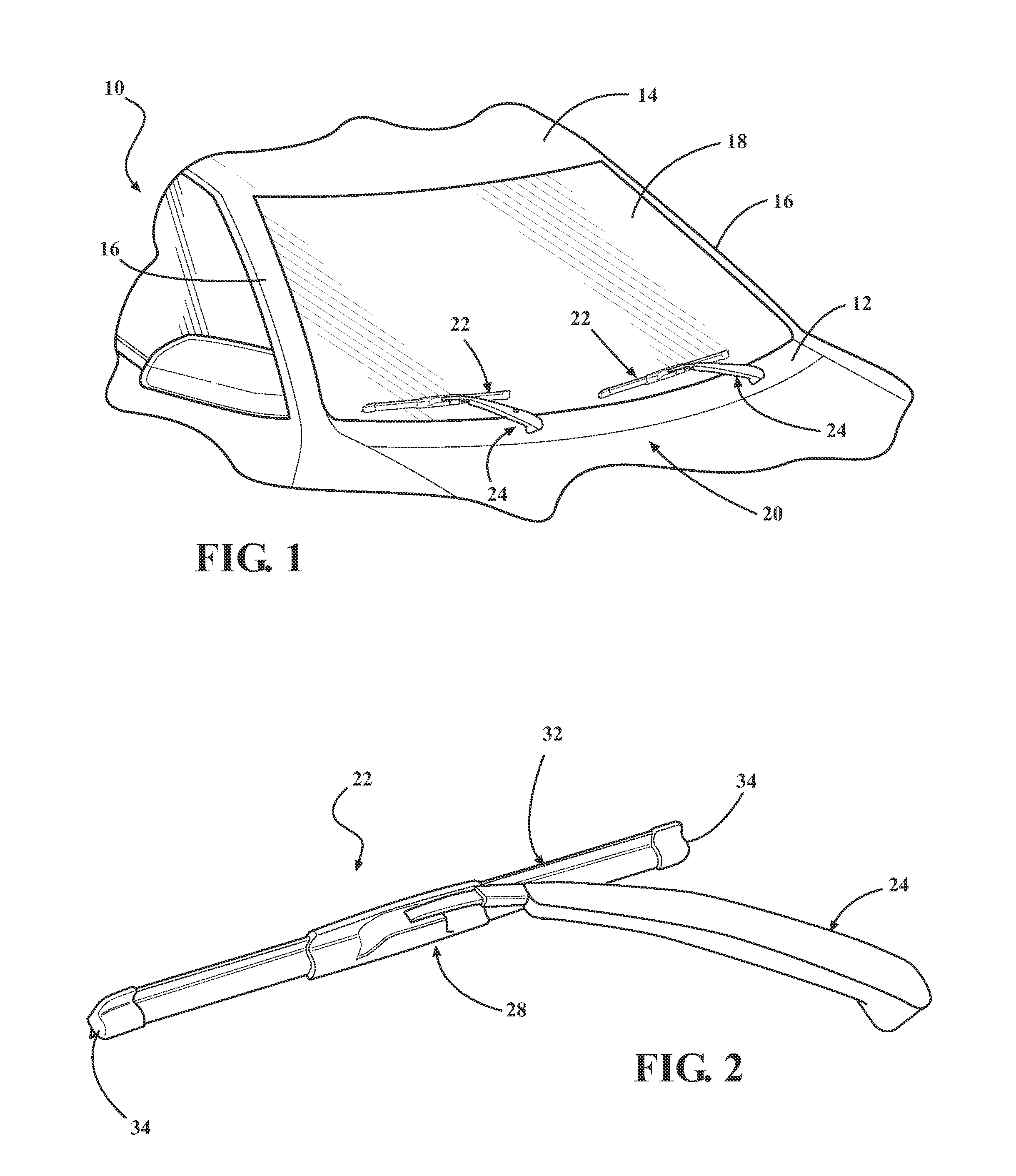
[0023]Referring now to the figures, where like numerals are used to designate like structure, a portion of a vehicle is illustrated at 10 in FIG. 1. The vehicle body includes a cowl 12, a roof 14, and a pair of laterally spaced front or “A” pillars 16 extending between the roof 14 and the cowl 12. The A-pillars 16, roof 14, and cowl 12 cooperate to define a generally rectangular perimeter, which supports a curved or “swept back” windshield 18.

[0024]A windshield wiper system is generally indicated at 20 in FIG. 1 and is employed to clean the glass windshield 18. In the representative example illustrated herein, the windshield wiper system 20 includes a pair of wiper assemblies, generally indicated at 22, and which correspond to the driver and passenger side of the vehicle 10. However, those having ordinary skill in the art will appreciate that the system could employ a single wiper assembly without departing from the scope of the invention. Each windshield wiper assembly 22 (hereina...


PUM


Abstract

A beam blade windshield wiper assembly including a wiping element and at least one elongated beam. A pair of end caps are operatively mounted to the longitudinal ends of the beam. The end caps include a body and inwardly extending legs that together with the body define a central channel that is adapted to receive the longitudinal ends of the wiping element and the beam. The legs include a retention tab that extends in the direction of the longitudinal axis of the beam and defines a terminal end. The beam includes a notch that corresponds with the retention tab such that the beam is received in the central channel. The retention tab is biased away from the channel until the terminal end of the tab comes into abutting engagement with the notch such that removal of the end cap is prevented.

Description

CROSS REFERENCE TO RELATED APPLICATIONS[0001]This application claims the benefit of U.S. provisional patent application entitled “Beam Blade Wiper Assembly Having Self-Locking End Cap,” having Ser. No. 61 / 416,953, and filed on Nov. 24, 2010.BACKGROUND OF THE INVENTION[0002]1. Field of the Invention[0003]The present invention relates, generally, to windshield wiper assemblies, and more specifically, to a beam blade windshield wiper assembly having a self-locking end cap.[0004]2. Description of the Related Art[0005]Conventional windshield wiper assemblies known in the related art include some type of blade assembly mounted to an arm which, in turn, is mounted adjacent the windshield and pivotally driven to impart reciprocal motion to the wiper blade assembly across the windshield. A rubber wiping element is supported by the blade assembly and contacts the windshield across the surface to be wiped. The wiper element often incorporates one or more metal strips which act to reinforce the...

Claims


Application Information

Patent Timeline
Patent Type & Authority Patents(United States)
IPC IPC(8): B60S1/38
CPCB60S1/3889B60S1/3879B60S1/381B60S1/3863B60S1/32B60S1/38
Inventor THIELEN, C. JOSEPHMOLL, KYLE
Owner TRICO PROD CORP
Why Eureka
Try Eureka