Method and system for fluidized lower leg protection

a technology of which is applied in the field of fluidized lower leg protection and support system, can solve the problems of low pressure on the inner positioner, insufficient alone to support the leg, and insufficient elevation of the lower leg and heel by itself, so as to reduce leg rotation and lock the knee, and keep the leg comfortable longer

Active Publication Date: 2014-10-14
MOLNLYCKE HEALTH CARE AB
View PDF6 Cites 10 Cited by
  • Summary
  • Abstract
  • Description
  • Claims
  • Application Information

AI Technical Summary

Benefits of technology

[0004]The present invention relates to a fluidized lower leg protection and support system and method. It is optimal to barely elevate the heel from the surface of the bed. This helps to minimize leg rotation and locking of the knee. The system can include an inner positioner. The inner positioner includes a bladder preferably filled with a fluidized particulate material to provide three-dimensional contouring to the lower leg and heel. The inner positioner has low pressure and is not sufficient alone to support the leg. The inner positioner has little or no flow characteristics unless an outside force is applied other than gravity. The inner positioner can displace and contour three-dimensionally as though it was fluid to the sides and top of the leg while not having flow characteristics that would result in migration of the medium under the force of gravity. The inner positioner can provide three-dimensional contouring to the Achilles tendon. The inner positioner can include a temperature regulating material for keeping the leg in an optimal range of skin temperature to keep the leg comfortable longer. The inner positioner can be shaped as a pad to mold to the underside portion of the lower leg and heel. Alternatively, the inner positioner can include various shapes to support the lower leg and heel. In one embodiment, the inner positioner also includes a portion which extends over a top portion of the leg (shin).
[0008]The system of the present invention can be a one size fits all and adapts to the size and shape of a patient's leg. The system maintains neutral alignment and helps prevent foot drop. The system gently but securely wraps the leg, helping to maintain constant heel position. The system promotes proper dorsiflexion without causing undue pressure on the lower limb.
[0009]The combination of the inner positioner including a fluidized medium along with the outer support including a ultra low pressure plenum creates sufficient support of the lower leg while responding to normal patient movement. The combination of the inner positioner and the outer support provides three-dimensional contouring to the lower leg and heel for micro adjustment while the outer support or boot is closed for minimizing friction and shear. This is not possible in conventional devices having the disadvantage that the inner chamber is not free to communicate with the leg without negatively affecting the functionality of the outer chamber. In general, the custom fitting protection can be used in such a way as to elevate the foot without “locking out the knee” due to three-dimensional molding and provide comfort to the skin. The natural contour of the leg can be maintained while eliminating harmful pressure to the heel, ankle, Achilles and foot. The system of the present invention can respond to the twisting of the leg without causing movement of the outer support. The system of the present invention can minimize shear forces that would be associated with a non-fluidized medium.

Problems solved by technology

The inner positioner has low pressure and is not sufficient alone to support the leg.
The ultra low pressure plenum is filled at a predetermined low pressure for distributing pressure along the length of the outer support, but not providing significant elevation of the lower leg and heel by itself.

Method used


Image

  • Method and system for fluidized lower leg protection
  • Method and system for fluidized lower leg protection
  • Method and system for fluidized lower leg protection

Examples


Embodiment Construction

[0035]Reference will now be made in greater detail to a preferred embodiment of the invention, an example of which is illustrated in the accompanying drawings. Wherever possible, the same reference numerals will be used throughout the drawings and the description to refer to the same or like parts.

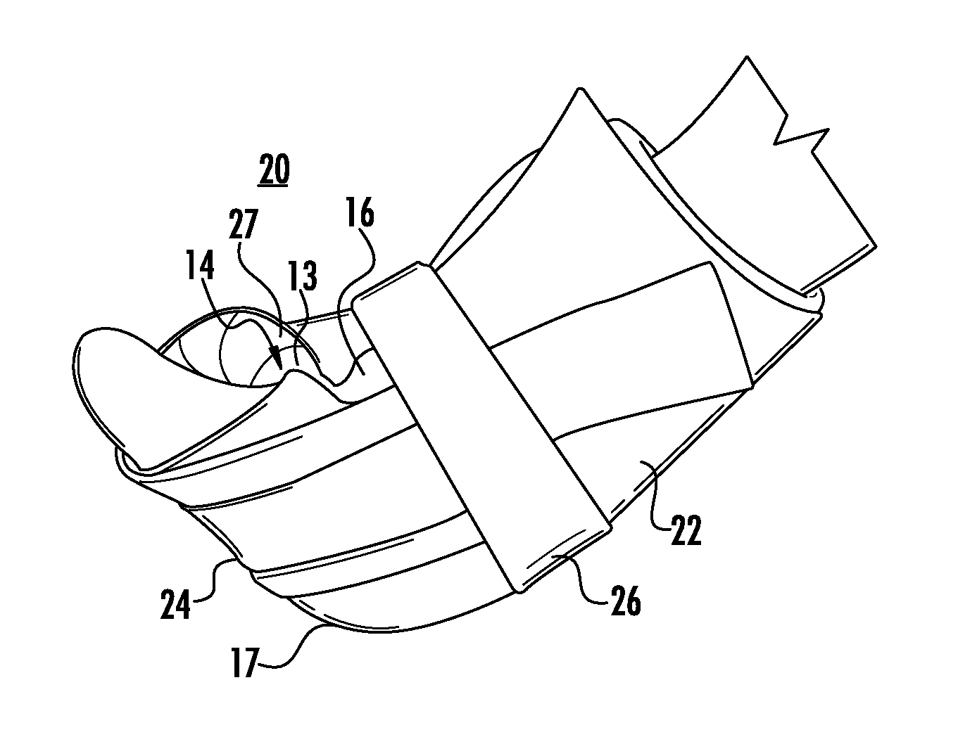
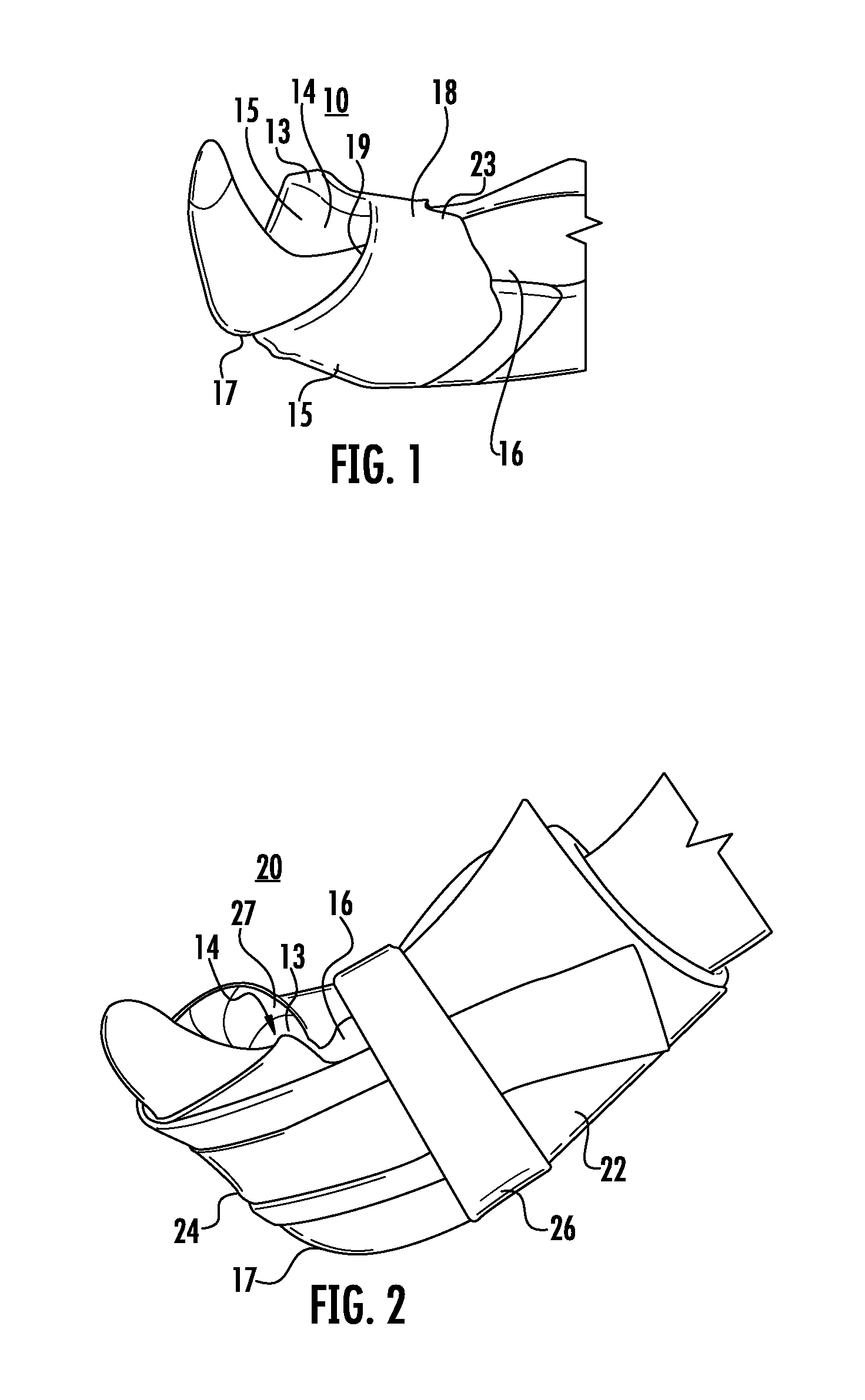
[0036]Fluidized lower leg protection and support system 10 includes inner positioner 14, as shown in FIG. 1. Inner positioner 14 is formed of bladder 13 including fluidized material 15 therein. Fluidized material 15 can be a particulate material including interstitial spaces between the particles. A lubricant can be present in the interstitial spaces. For example, the lubricant can be a particulate material having a lower coefficient of friction, such as a powder. The volume of the particulate material can be controlled for controlling the interstitial air within the fluidized medium.

[0037]Bladder 13 is filled with fluidized material 15 which can retain its shape after sculpting. The flowa...


PUM


Abstract

The present invention relates to a fluidized lower leg protection and support system and method. The system can include an inner positioner. The inner positioner can displace and contour three-dimensionally as though it was fluid to the sides and top of the leg while not having flow characteristics that would result in migration of the medium under the force of gravity. The system can also include an outer support which is received over the inner positioner. The outer support can be in the shape of an open boot. The outer support can include an ultra low pressure plenum. The ultra low pressure plenum is filled at a predetermined low pressure for distributing pressure along the length of the outer support, but not providing significant elevation of the lower leg and heel by itself.

Description

CROSS REFERENCE TO RELATED APPLICATION[0001]This application claims the benefit of U.S. Provisional Patent Application No. 61 / 614,782 filed Mar. 23, 2012 and U.S. Provisional Patent Application No. 61 / 495,082, filed Jun. 9, 2011, the entireties of which applications are hereby incorporated by reference into this application.BACKGROUND OF THE INVENTION[0002]Conventional supports provide a polyester filled or foam boot for support of a lower leg. Other conventional supports include an ankle foot orthotic (AFO) or foot wrap. Another conventional support includes an air chamber in a boot configuration. The air chamber supports a leg and heel above a surface of a bed patient when lying in a supine or side lying position, such as in a hospital bed. The conventional supports have the disadvantage that pressure is applied to the heel or leg for maintaining the heel above the surface of the bed. In addition, the leg can be raised too high such that joints can lock, nerves can be potentially ...

Claims


Application Information

Patent Timeline
Patent Type & Authority Patents(United States)
IPC IPC(8): A61F5/00
CPCA61F5/0111A61G99/00A61G7/08A61H9/005A61H2201/0103A61H1/008A61G7/0755
Inventor PURDY, WILLIAMPURDY, ROBERT
Owner MOLNLYCKE HEALTH CARE AB
Why Eureka
Try Eureka