Optical system demonstrating improved resistance to optically degrading external effects
What is AI technical title?
AI technical title is built by PatSnap AI team. It summarizes the technical point description of the patent document.
a technology of optical system and external effect, applied in the field of optical system, can solve the problem of unfavorable alteration of the angle of refraction at the array surface, and achieve the effect of increasing the counterfeit resistance of these materials
Active Publication Date: 2014-10-21
VISUAL PHYSICS LLC (US)
View PDF275 Cites 42 Cited by
Summary
Abstract
Description
Claims
Application Information
AI Technical Summary
This helps you quickly interpret patents by identifying the three key elements:
Problems solved by technology
Method used
Benefits of technology
Benefits of technology
[0014]By way of the present invention, the inventors have found that in addition to providing the system with improved resistance to optically degrading external effects, the use of a material having a substantially or measurably different refractive index (e.g., the second material) over the image icon focusing elements may increase the F number of the focusing elements so as to cause exaggerated optical effects. For example, upon tilting the inventive system, synthetic images may appear deeper or further above the system, or may appear to move faster, depending on the desired optical effect.
[0017]The embodiment in which the second material totally embeds the focusing element array may be used in the form of, for example, a security strip, thread, patch, or overlay and mounted to a surface of, or at least partially embedded within a fibrous or non-fibrous sheet material (e.g., banknote, passport, identification or ID card, credit card, label), or commercial product (e.g., optical disks, CDs, DVDs, packages of medical drugs), etc., for authentication purposes. This embodiment may also be used in the form of a standalone product (e.g., a substrate for subsequent printing or personalization), or in the form of a non-fibrous sheet material for use in making, for example, banknotes, passports, and the like. As will be readily appreciated by those skilled in the art, the visual effects offered by the inventive optical system serve to greatly increase the counterfeit resistance of these materials.
Problems solved by technology
In particular, the synthetic image or images projected by these materials tend to disappear, defocus, or blur when such a disrupting material is applied to the focusing element array surface, the disrupting material causing an undesirable alteration in the angle of refraction at the array surface.
Method used
Image
Click on the blue label to locate the original text in one second.
Reading with bidirectional positioning of images and text.
Examples
Embodiment Construction
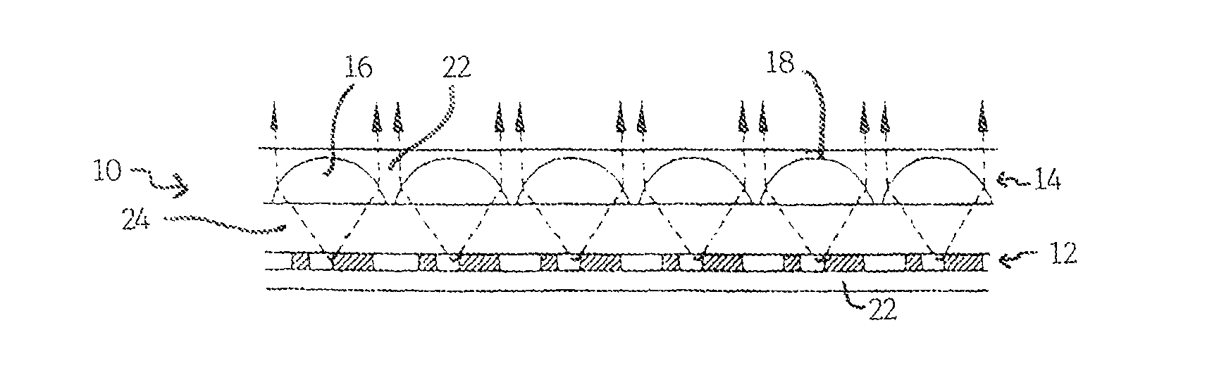
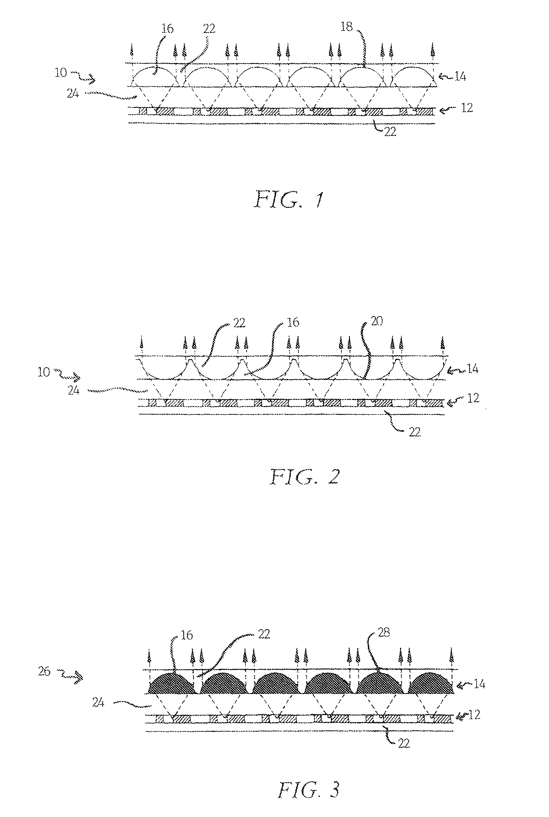
[0027]As described in detail in, for example, U.S. Pat. No. 7,333,268 to Steenblik et al., the focal length of the focusing elements in micro-optic materials determines the optical separation of the focusing elements from an image icon array. In other words, the arrays in these prior art micro-optic materials are positioned so as to align the focal point of each focusing element with their associated image icon(s). When the focal point lies on or within the image icon array, the synthetic image is in sharp focus. When, however, the focal point lies above or below the image icon array, the synthetic image is blurry and out of focus.
[0028]By way of exemplary embodiments of the present invention, the geometry of the focusing elements (e.g., microlenses) and the refractive indices of both the first material and the second material are tailored to achieve the desired focal length and thus the optical separation (if any) between arrays. Without such tailoring, the focal length of the focu...
PUM
Property
Measurement
Unit
total height
aaaaa
aaaaa
total depth
aaaaa
aaaaa
focal length
aaaaa
aaaaa
Abstract
A system for projecting one or more synthetic optical images, which demonstrates improved resistance to optically degrading external effects, is provided. The inventive system serves to lock the focal length of the focusing elements in place. In other words, no other transparent materials or layers brought into contact with the inventive system will serve to materially alter the focal length or the optical acuity of synthetic images formed by the system.
Description
RELATED APPLICATIONS[0001]This application is a continuation-in-part of U.S. patent application Ser. No. 11 / 771,623, filed Jun. 29, 2007 (now U.S. Pat. No. 8,120,855), and of U.S. patent application Ser. No. 11 / 932,468, filed Oct. 31, 2007 (now U.S. Pat. No. 8,111,462), both of which are divisionals of and claim priority to U.S. patent application Ser. No. 10 / 995,859, filed Nov. 22, 2004 (now U.S. Pat. No. 7,333,268), which claims priority to U.S. Provisional Patent Application Ser. No. 60 / 524,281, filed Nov. 21, 2003, U.S. Provisional Patent Application Ser. No. 60 / 538,392, filed Jan. 22, 2004, and U.S. Provisional Patent Application Ser. No. 60 / 627,234, filed Nov. 12, 2004, all of which are hereby incorporated herein by reference in their entirety.TECHNICAL FIELD[0002]The present invention generally relates to an optical system for projecting one or more synthetic optical images, which demonstrates improved resistance to optically degrading external effects.BACKGROUND AND SUMMARY ...
Claims
Application Information
Patent Timeline
Application Date:The date an application was filed.
Publication Date:The date a patent or application was officially published.
First Publication Date:The earliest publication date of a patent with the same application number.
Issue Date:Publication date of the patent grant document.
PCT Entry Date:The Entry date of PCT National Phase.
Estimated Expiry Date:The statutory expiry date of a patent right according to the Patent Law, and it is the longest term of protection that the patent right can achieve without the termination of the patent right due to other reasons(Term extension factor has been taken into account ).
Invalid Date:Actual expiry date is based on effective date or publication date of legal transaction data of invalid patent.

