Tetrachromatic color filter array for reflective display

a color filter array and tetrachromatic technology, applied in the field of electro-optic displays and color filters, can solve the problems of preventing their widespread use, inadequate service life of these displays, and gas-based electrophoretic media being susceptible to the same types of problems, so as to improve the appearance of color images on electro-optic displays

Active Publication Date: 2014-10-28
E INK CORPORATION
View PDF63 Cites 116 Cited by
  • Summary
  • Abstract
  • Description
  • Claims
  • Application Information

AI Technical Summary

Benefits of technology

[0030]It has now been found that the appearance of color images on electro-optic displays can be improved by using a new set of four primary colors. The result of using the new set of four primary colors is a compromise between the aforementioned properties of RGB and CMY primaries; more specifically, the new set of four primaries produces red, green and blue color saturation greater than that achieved by CMY primaries, while producing a white state better than that achieved with RGB primaries. The resulting properties render color images more attractive to the human eye than those achieved with either RGB or CMY primaries. In one set of embodiments, the four primary colors can be selected as a set of two pairs of hues, P1 / P3 and P2 / P4. Hue pair P1 / P3 and / or hue pair P2 / P4 can be selected such that they average to gray.

Problems solved by technology

Nevertheless, problems with the long-term image quality of these displays have prevented their widespread usage.
For example, particles that make up electrophoretic displays tend to settle, resulting in inadequate service-life for these displays.
Such gas-based electrophoretic media appear to be susceptible to the same types of problems due to particle settling as liquid-based electrophoretic media, when the media are used in an orientation which permits such settling, for example in a sign where the medium is disposed in a vertical plane.
Indeed, particle settling appears to be a more serious problem in gas-based electrophoretic media than in liquid-based ones, since the lower viscosity of gaseous suspending fluids as compared with liquid ones allows more rapid settling of the electrophoretic particles.
Although improvements have been achieved with RGBW color filters, it has been found that when an RGBW filter is used with an electro-optic display and the red, green and blue pixels use reasonably saturated red, green and blue colors, the white state of the display is rather poor.

Method used


Image

  • Tetrachromatic color filter array for reflective display
  • Tetrachromatic color filter array for reflective display
  • Tetrachromatic color filter array for reflective display

Examples


Embodiment Construction

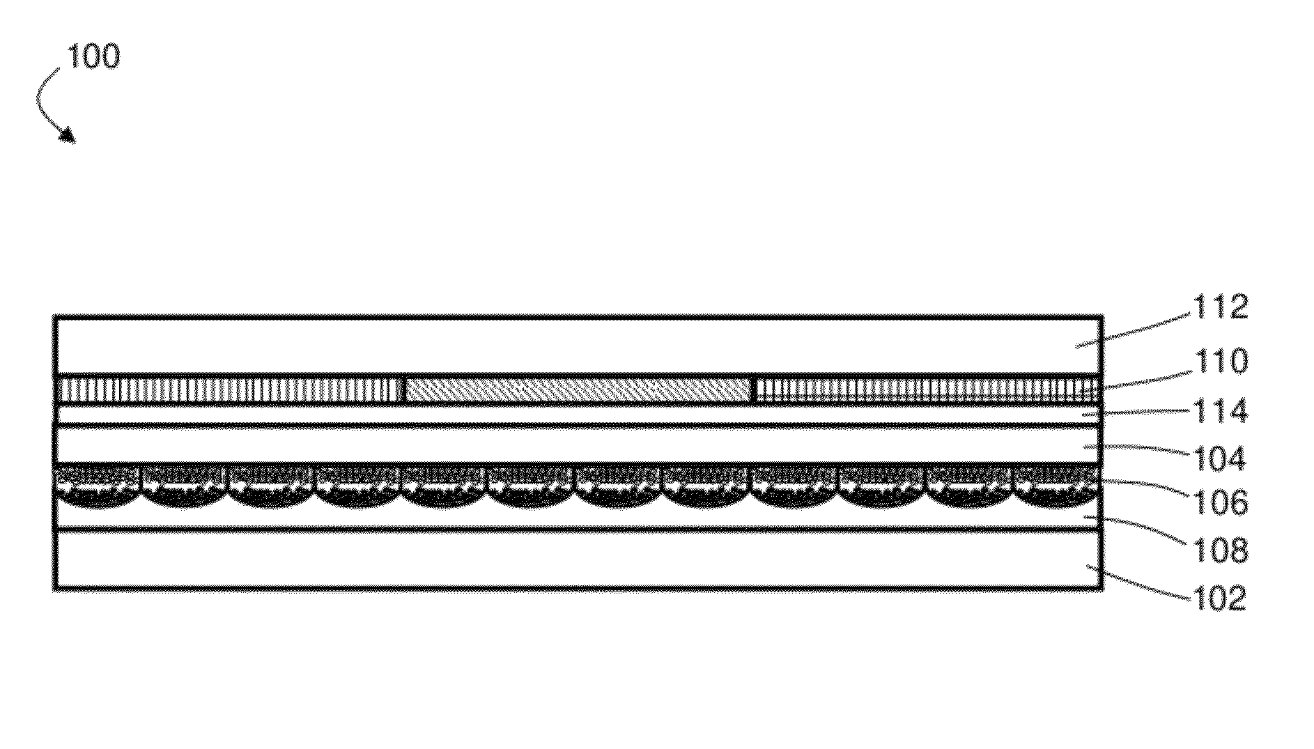
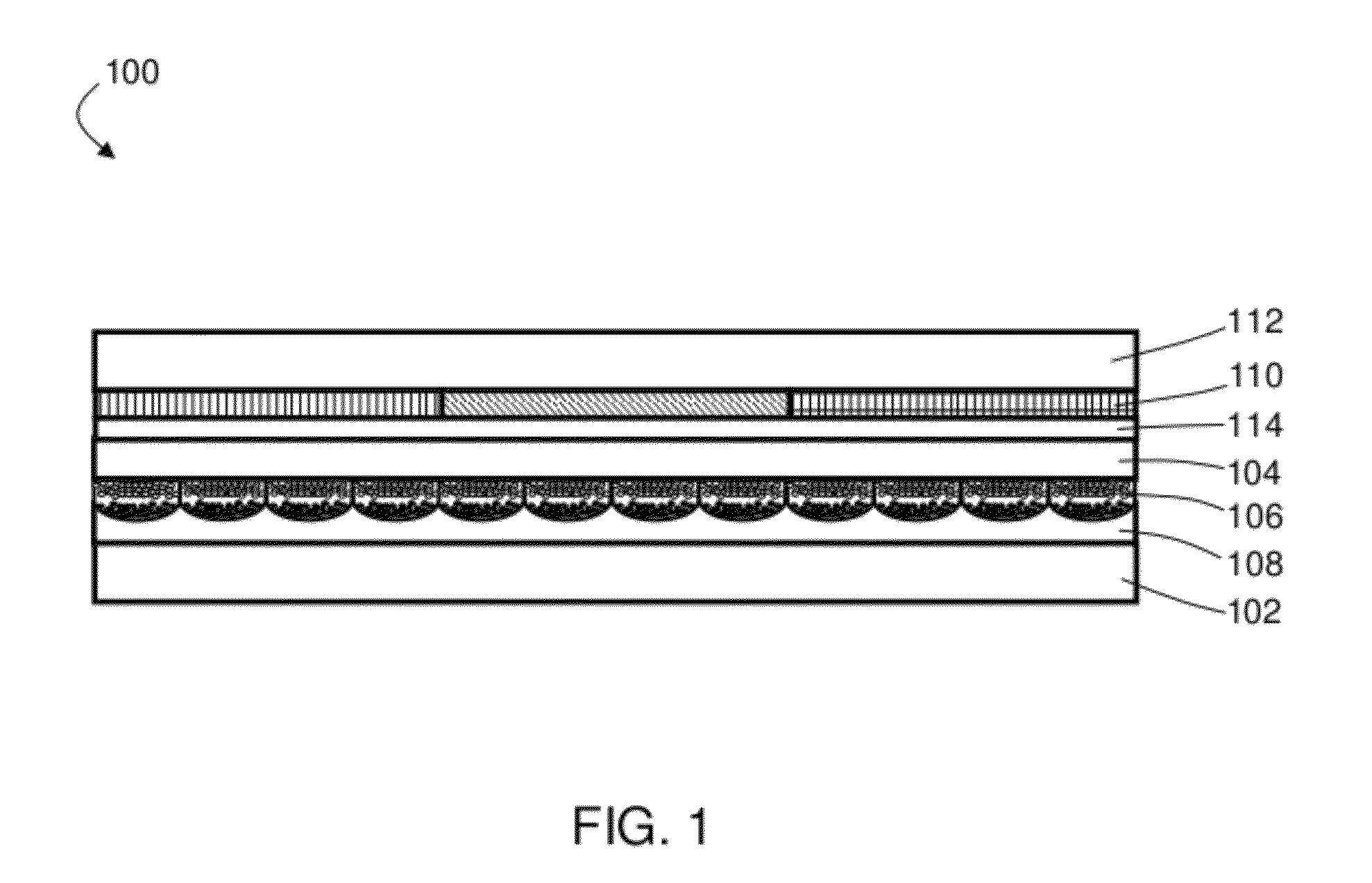
[0047]As previously mentioned, color filter arrays comprising four primary colors are provided. Also provided are electro-optic displays using such color filter arrays.

[0048]The color filter arrays described herein can be produced by selecting four primary color hues, referred to as P1, P2, P3, and P4 herein. Hues P1-P4 can include two pairs of hues: a first hue pair P1 and P3 (i.e., P1 / P3), and a second hue pair P2 and P4 (i.e., P2 / P4). In some embodiments, hues P1-P4 can be selected such that each pair of hues averages to a neutral gray. For example, the combination of hues P1 and P3 and / or the combination of hues P2 and P4 can average to gray. Such an effect can be achieved by selecting hues with certain positions on the a*b* plane of the La*b* color space.

[0049]FIGS. 3A-3B include exemplary plots of the a*b* plane in the La*b* color space, which can be used to illustrate the selection of hues appropriate for use in various embodiments described herein. As used herein, “La*b* col...


PUM

PropertyMeasurementUnit
anglesaaaaaaaaaa
anglesaaaaaaaaaa
angle h2aaaaaaaaaa

Abstract

A tetrachromatic color filter array comprises multiple pixels, each of which comprises first, second, third and fourth sub-pixels having first, second, third and fourth hues, P1, P2, P3 and P4 respectively, these first, second, third and fourth hues having first, second and third hue angles, h1, h2, h3 and h4 respectively. The hues of the sub-pixels such that h3 equals h1+(180°±10°) and h4 equals h2+(180°±10°) in the a*b* plane of the La*b* color space.

Description

BACKGROUND OF INVENTION[0001]This invention relates to electro-optic displays and color filters for use in such displays.[0002]The term “electro-optic”, as applied to a material or a display, is used herein in its conventional meaning in the imaging art to refer to a material having first and second display states differing in at least one optical property, the material being changed from its first to its second display state by application of an electric field to the material. Although the optical property is typically color perceptible to the human eye, it may be another optical property, such as optical transmission, reflectance, or luminescence or, in the case of displays intended for machine reading, pseudo-color in the sense of a change in reflectance of electromagnetic wavelengths outside the visible range.[0003]The terms “bistable” and “bistability” are used herein in their conventional meaning in the art to refer to displays comprising display elements having first and seco...

Claims


Application Information

Patent Timeline
Patent Type & Authority Patents(United States)
IPC IPC(8): G02B5/22G02F1/1335G02B26/00G02B26/08G02B5/20G02F1/167G02F1/29G02F1/1677
CPCG02F2203/055G02B5/201G02F1/133514G02F1/167G02B5/22G02F1/1677
Inventor PAOLINI, JR., RICHARD J.TELFER, STEPHEN J.BOUCHARD, ALAINATKINSON, JOHN
Owner E INK CORPORATION
Why Eureka
Try Eureka