
System and method for high accuracy gas refill in a two chamber gas discharge laser system

a gas discharge laser and high-accuracy technology, which is applied in the field of laser systems, can solve the problems of reducing laser efficiency, difficult to achieve accurate refills, and changing laser performance, and achieves significantly more accurate performance, less gas, and accurate performance

Active Publication Date: 2014-10-28
CYMER INC
View PDF5 Cites 2 Cited by
  • Summary
  • Abstract
  • Description
  • Claims
  • Application Information

AI Technical Summary

Benefits of technology

[0013]A system and method for automatically and accurately performing refills of the gas in the chambers of a two chamber gas discharge laser such as a MOPA excimer laser is disclosed. Control of the refill process is based upon calculation of the actual amount of gas added to the chambers according to gas equations, rather than merely the pressure of the gas as in the prior art. The impact of both temperature variation and the pipe line volume is also considered by the use of such equations. By allowing for these factors, refills may be performed significantly more accurately than with the process of the prior art, and potentially with the use of less gas.

Problems solved by technology

While excimer lasers may be built with a single chamber light source, the conflicting design demands for more power and reduced spectral bandwidth have meant a compromise in performance in such single chamber designs.
This causes a decrease in the laser efficiency which is seen, for example, as an increase in discharge voltage required to create a given desired pulse energy.
However, refills are extremely disruptive as the laser be shut off during the refill process, and thus the lithographic exposure of chips must also be paused in a controlled manner at the same time and then restarted when the laser is again operational to avoid improper processing of the chips.
However, the performance of the laser still tends to change over time in such a way that injects become inadequate to compensate, and so refills are still performed at regular intervals.
However, it is difficult to achieve accurate refills, for two main reasons.
First, refills are generally based solely on pressure, and do not measure or compensate for variations in temperature which can result in significant variations in the final pressure in the laser chambers.
Second, refill protocols and algorithms typically only consider the laser chamber volumes and do not take into account the gas that is present in the pipes between the gas tanks and the laser chambers.

Method used


Image

  • System and method for high accuracy gas refill in a two chamber gas discharge laser system
  • System and method for high accuracy gas refill in a two chamber gas discharge laser system
  • System and method for high accuracy gas refill in a two chamber gas discharge laser system

Examples


Embodiment Construction

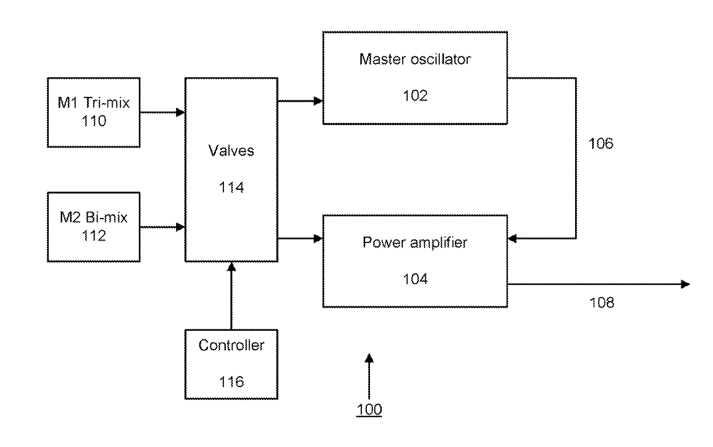
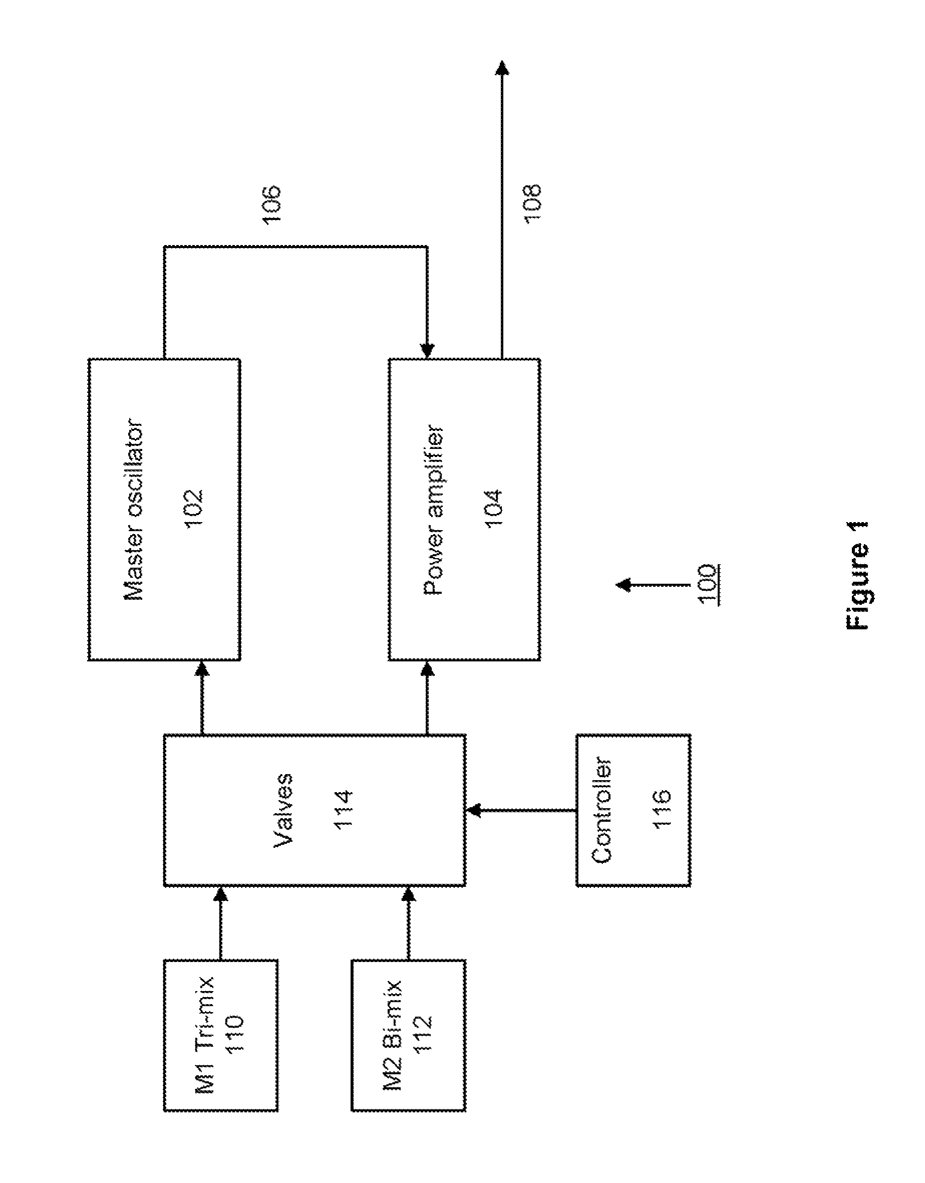
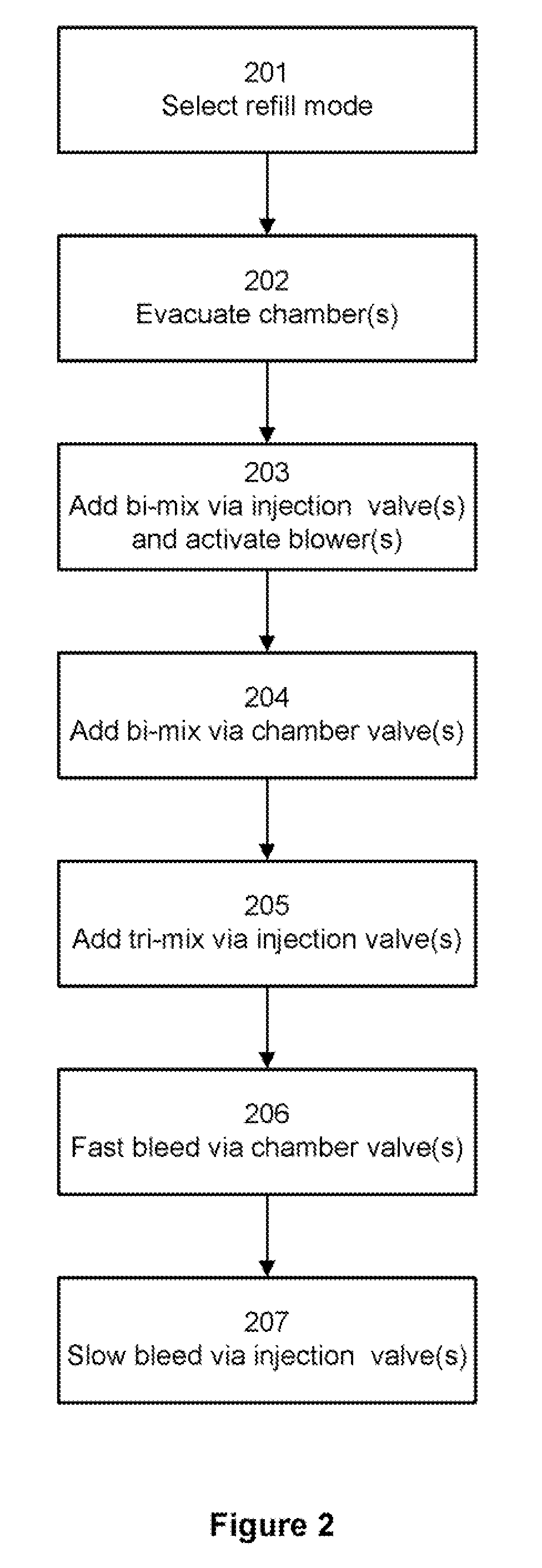
[0020]The present application describes a method and system for automatically and accurately performing refills of the gas in the chambers of a two chamber gas discharge laser such as a MOPA excimer laser. It is expected that an automated refill process will result in increased accuracy and mitigate or eliminate many of the issues associated with previous refills. Control of the refill process is based upon calculation of the amount of gas added to the chambers according to gas equations using both temperature and pressure, rather than merely relying on the pressure of the gas, and thus also takes into account the impact of temperature variations. The described process also takes gas left over in the pipe line volume into account. By allowing for these factors in the process, refills may be performed significantly more accurately than with the processes of the prior art, and possibly with the use of less gas.

[0021]A simplified block diagram of a gas replenishment system 100 for a du...


PUM


Abstract

Systems and methods for automatically performing a high accuracy gas refill in a laser chamber of a two chamber gas discharge laser such as an excimer laser are disclosed. Based upon a target pressure and halogen concentration that is either predetermined or entered by a user, and with no further user action, a non-halogen containing gas is added to the chamber to a first pressure, followed by the addition of halogen containing gas to a second pressure which is greater than a target pressure for the chamber, such that the halogen content in the gas at the second pressure is at a desired concentration. The gas in the chamber is bled until the pressure drops to the target pressure. The amount of non-halogen containing gas added is estimated automatically, and the amount of halogen containing gas is measured so that the desired concentration is obtained, taking into account both temperature and any gas remaining in the fill pipes from prior laser operation.

Description

FIELD OF THE INVENTION[0001]The present invention relates generally to laser systems. More specifically, the invention relates to performing refills of the gas in the chambers of a gas discharge laser, such as a two chamber Master Oscillator-Power Amplifier excimer laser.BACKGROUND OF THE INVENTION[0002]One type of gas discharge laser used in photolithography is known as an excimer laser. An excimer laser typically uses a combination of a noble gas, such as argon, krypton, or xenon, and a reactive gas such as fluorine or chlorine. The excimer laser derives its name from the fact that under the appropriate • conditions of electrical stimulation and high pressure, a pseudo-molecule called an excimer (or in the case of noble gas halides, an exciplex) is created, which can only exist in an energized state and can give rise to laser light in the ultraviolet range.[0003]Excimer lasers are widely used in high-resolution photolithography machines, and are thus one of the critical technologi...

Claims


Application Information

Patent Timeline
Patent Type & Authority Patents(United States)
IPC IPC(8): H01S3/036H01S3/22H01S3/223
CPCH01S3/036H01S3/2366H01S3/225H01S3/2308H01S3/22
Inventor JIANG, RUITHORNES, JOSHUA JONRIGGS, DANIEL JASONO'BRIEN, KEVIN MICHAEL
Owner CYMER INC
Learn More