Access door unit and method of installing door unit

a door unit and door technology, applied in the field of enclosures, can solve the problems of cumbersome manipulation of the flap door, not wide open, difficult to see, and not easy nor convenient to use, and achieve the effect of convenient assembly and installation and convenient assembly

Inactive Publication Date: 2014-11-04
DIXON JR NICHOLAS E
View PDF22 Cites 14 Cited by
  • Summary
  • Abstract
  • Description
  • Claims
  • Application Information

AI Technical Summary

Benefits of technology

[0008]The present invention provides an access door unit designed to overcome the above-described drawbacks and satisfy the need for versatile, convenient and easy access to inside an enclosure, such as a batting cage. Specifically, the access door unit provides a doorway structure and a door which can be easily assembled and installed to provide the access door unit in a self-supporting relationship to the batting cage at any one of various different locations about the perimeter of the batting cage. The doorway structure has its own base support members which allow the unit to be self-standing, or free-standing, and thus installable in the self-supporting relationship at any of the different locations. Also, in one exemplary embodiment the door utilizes a double layer sock net which is easy to assemble on a peripheral door frame to form a closure panel of the door. The present invention also provides a method of installation of the doorway frame and door.

Problems solved by technology

The flap door typically is cumbersome to manipulate and does not open wide enough for easy passage with equipment.
Additionally, they are difficult to see and thus find in that they do not appear distinct from the net.
Thus, they are neither easy nor convenient to use.
Lifting the cage wall can be difficult for many users in that a user has to stoup over or bend down.
Furthermore, requiring that a wall be capable of being lifted for allowing entry or exit can also prevent the batting cage user from safely anchoring or “staking or weighting” the bottom edges of the batting cage walls to prevent passage of balls from the cage.
The approach of this design patent would appear to be dependent on and limited to the batting cages having the particular arrangement of the extended framework.

Method used


Image

  • Access door unit and method of installing door unit
  • Access door unit and method of installing door unit
  • Access door unit and method of installing door unit

Examples


Embodiment Construction

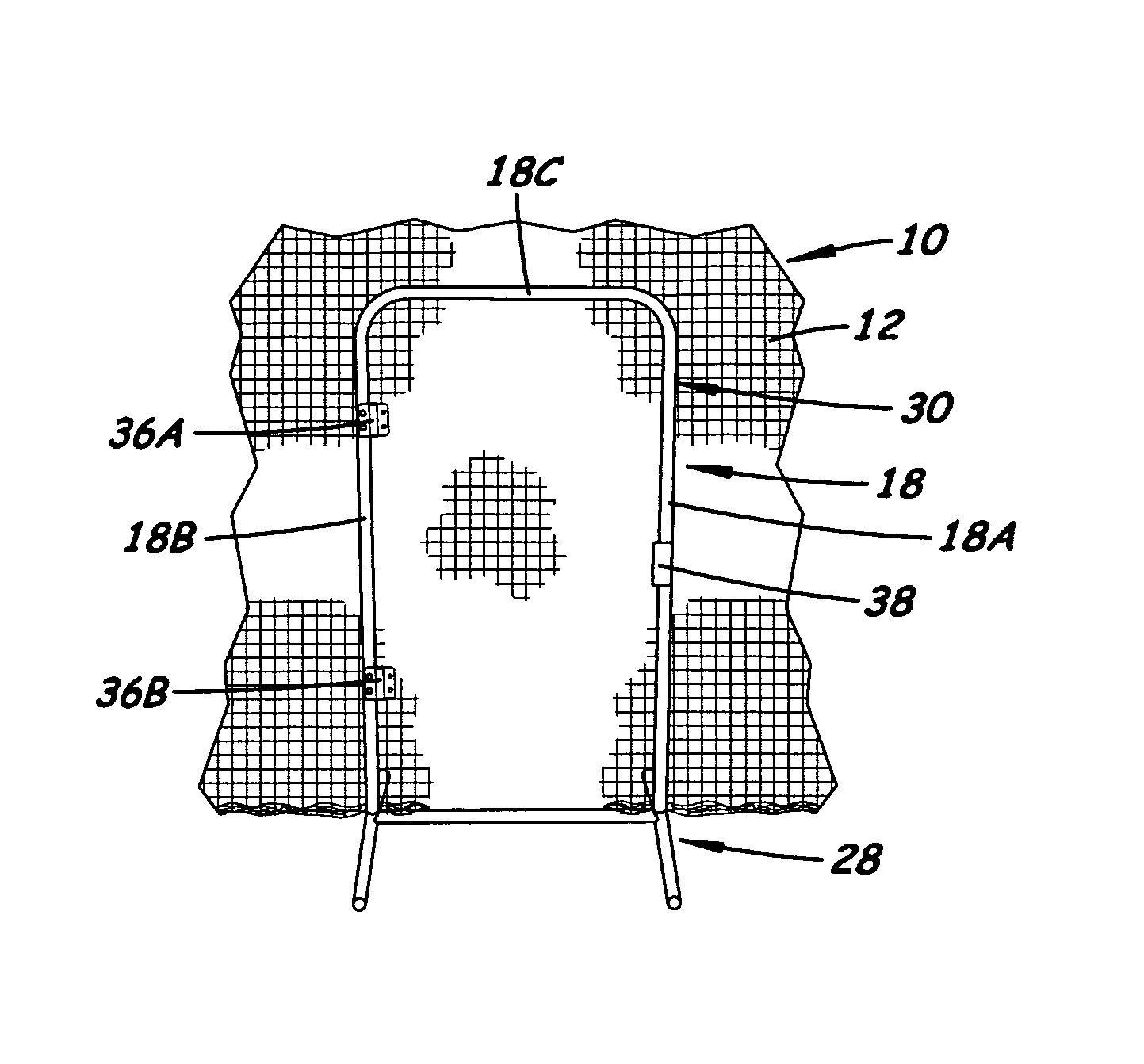
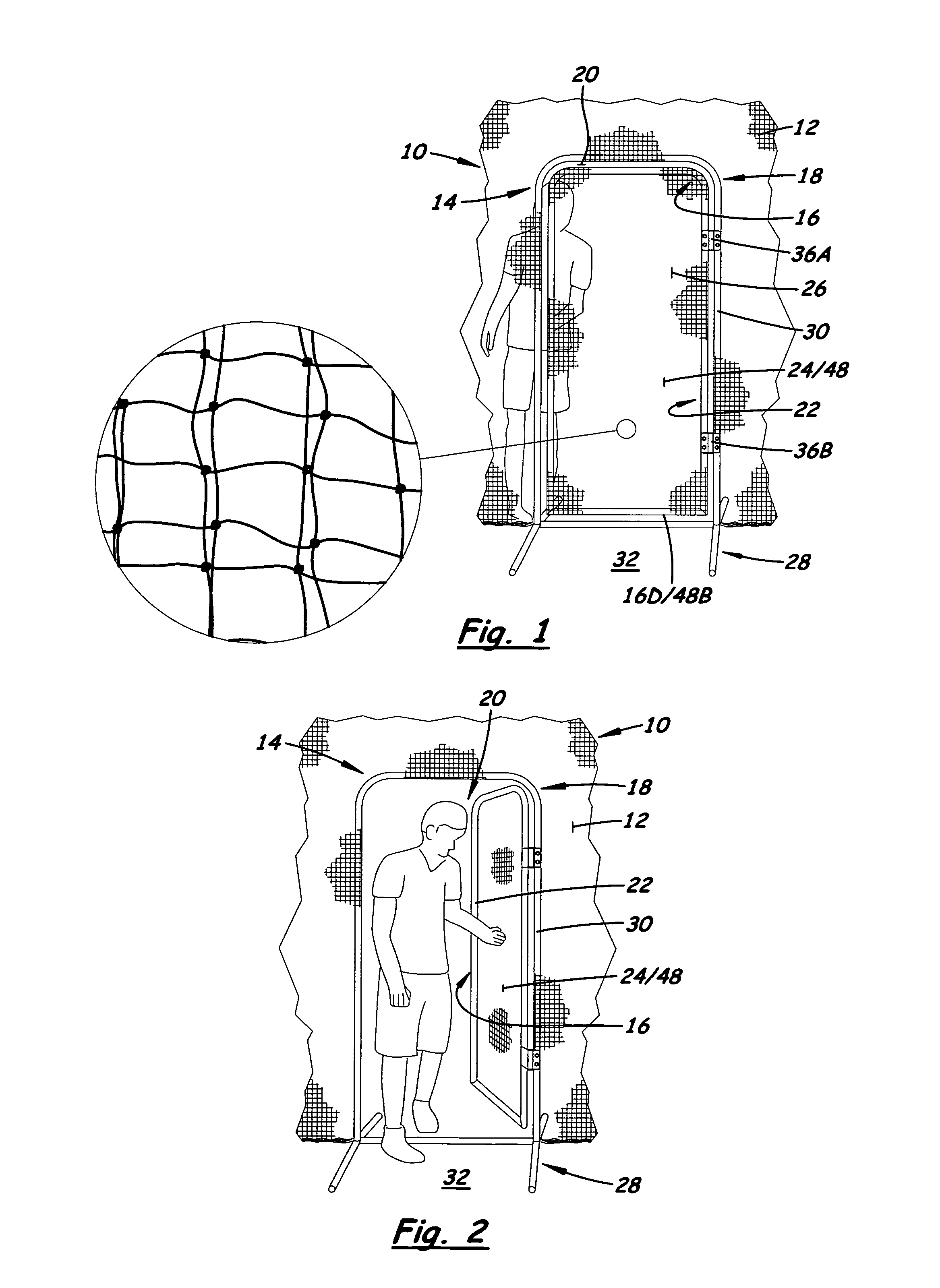
[0026]Referring to the drawings, and particularly to FIGS. 1 and 2, there is illustrated a wall of a conventional batting cage 10 formed by a vertically suspended or hanging net 12 unattached or free at its lower edge. (In various of the figures portions of the net 12 have been omitted for purposes of clarity and convenience in illustration.) The net 12 may be fabricated from strands of any suitable, preferably flexible, material, such as fabric, plastic or metallic woven cord or wire. Also shown is an exemplary embodiment of an access door unit 14, which constitutes one aspect of the present invention, installed or built into the net 12 of the batting cage 10. The access door unit 14 permits easy and convenient entry into and exit from the batting cage 10, as shown in FIGS. 1 and 2. While the access door unit 14 is disclosed herein installed into the wall or net 12 of the batting cage 10, it should be understood that the unit 14 also may be installed in a wall of a tent or various ...


PUM


Abstract

An access door unit includes a door, a doorway structure, and elements for pivotally attaching the door to the doorway structure. The doorway structure has an outer perimeter frame and a base affixed thereon. The base has support members extending in transverse relation to and outwardly in opposite directions from the outer perimeter frame and adapted to rest on a generally level support surface such that the outer perimeter frame extends upright from the base enabling the doorway structure to assume a free-standing, self-supporting orientation on the support surface. The outer perimeter frame of the doorway structure defines a passage large enough to fit the door and permit entry or exit through the passage when the door is opened.

Description

[0001]This patent application claims the benefit of U.S. provisional application No. 61 / 571,105 filed Jun. 21, 2011. The disclosure of said provisional application is hereby incorporated herein by reference thereto.BACKGROUND OF THE INVENTION[0002]1. Field of the Invention[0003]The present invention generally relates to access to enclosures, such as batting cages, and, more particularly, is concerned with an access door unit and a method of installing the door unit.[0004]2. Description of the Prior Art[0005]Enclosures, for example batting cages, typically do not come with or have a conventional or regular style door, one that opens, closes, latches, and allows users with baseball equipment to entry and exit easily to and from the batting cage. There are some batting cages that have what is called a “flap door”, built into the net of the batting cage. The flap door typically is an overlapped piece of the net configured to form a flap that covers an opening in the netting. To enter or...

Claims


Application Information

Patent Timeline
Patent Type & Authority Patents(United States)
IPC IPC(8): E06B7/28
CPCA63B71/022A63B2069/0008
Inventor DIXON, JR., NICHOLAS, E.
Owner DIXON JR NICHOLAS E
Why Eureka
Try Eureka