Remotely controlled apparatus for downhole applications and methods of operation

a remote control and subterranean technology, applied in the direction of borehole/well accessories, sealing/packing, survey, etc., can solve the problems of expensive pistons, expensive seals disposed around a complex shaped, and the disadvantage of narrowing the borehol

Active Publication Date: 2014-11-11
BAKER HUGHES OILFIELD OPERATIONS LLC
View PDF148 Cites 18 Cited by
  • Summary
  • Abstract
  • Description
  • Claims
  • Application Information

AI Technical Summary

Problems solved by technology

While adding additional casing allows a borehole to reach greater depths, it has the disadvantage of narrowing the borehole.
Also, designs of some conventional expandable reamer assemblies fail to help blade retraction when jammed and pulled upward against the borehole casing.
Furthermore, some conventional hydraulically actuated reamers utilize expensive seals disposed around a very complex shaped and expensive piston, or blade, carrying cutting elements.
These seals are feared to possibly leak after extended usage.
For instance, bi-center and reamer wing assemblies are limited in the sense that the pass through diameter of such tools is nonadjustable and limited by the reaming diameter.
Furthermore, conventional bi-center and eccentric bits may have the tendency to wobble and deviate from the path intended for the borehole.
Conventional expandable reaming assemblies, while sometimes more stable than bi-center and eccentric bits, may be subject to damage when passing through a smaller diameter borehole or casing section, may be prematurely actuated, and may present difficulties in removal from the borehole after actuation.

Method used


Image

  • Remotely controlled apparatus for downhole applications and methods of operation
  • Remotely controlled apparatus for downhole applications and methods of operation
  • Remotely controlled apparatus for downhole applications and methods of operation

Examples


Embodiment Construction

[0034]The illustrations presented herein are, in some instances, not actual views of any particular expandable apparatus, but are merely idealized representations that are employed to describe the present invention. Additionally, elements common between figures may retain the same numerical designation.

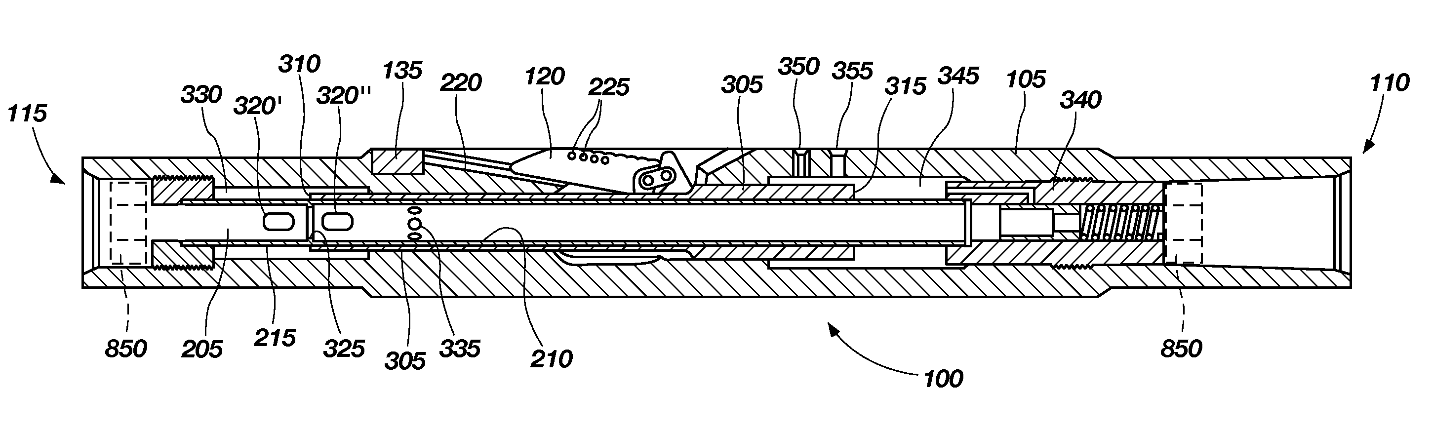
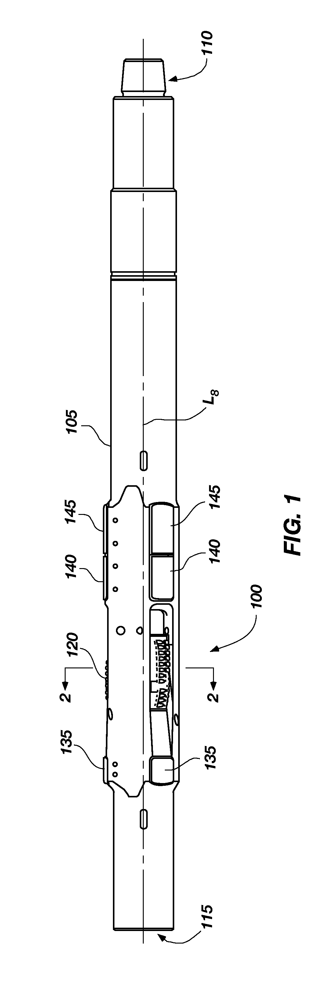
[0035]Various embodiments of the disclosure are directed to expandable apparatus. By way of example and not limitation, an expandable apparatus may comprise an expandable reamer apparatus, an expandable stabilizer apparatus or similar apparatus. FIG. 1 illustrates an expandable apparatus 100 according to an embodiment of the disclosure comprising an expandable reamer. The expandable reamer may be similar to the expandable apparatus described in U.S. Patent Publication No. 2008 / 0128175, now U.S. Pat. No. 7,900,717, issued Mar. 8, 2011, the entire disclosure of which is incorporated herein by this reference.

[0036]The expandable apparatus 100 may include a generally cylindrical tubular b...


PUM


Abstract

An apparatus for use downhole is disclosed that, in one configuration includes a downhole tool configured to operate in an active position and an inactive position and an actuation device, which may include a control unit. The apparatus includes a telemetry unit that sends a first pattern recognition signal to the control unit to move the tool into the active position and a second pattern recognition signal to move the tool into the inactive position. The apparatus may be used for drilling a subterranean formation and include a tubular body and one or more extendable features, each positionally coupled to a track of the tubular body, and a drilling fluid flow path extending through a bore of the tubular body for conducting drilling fluid therethrough. A push sleeve is disposed within the tubular body and coupled to the one or more features. A valve assembly is disposed within the tubular body and configured to control the flow of the drilling fluid into an annular chamber in communication with the push sleeve; the valve assembly comprising a mechanically operated valve and / or an electronically operated valve. Other embodiments, including methods of operation, are provided.

Description

CROSS-REFERENCE TO RELATED APPLICATIONS[0001]This application claims the benefit of U.S. Provisional Application Ser. No. 61 / 247,162, filed Sep. 30, 2009, entitled “Remotely Activated and Deactivated Expandable Apparatus for Earth Boring Applications,” and claims the benefit of U.S. Provisional Patent Application Ser. No. 61 / 377,146, entitled “Remotely-Controlled Device and Method for Downhole Actuation” filed Aug. 26, 2010, the disclosure of each of which of the foregoing applications is hereby incorporated herein by this reference in its entirety.TECHNICAL FIELD[0002]Embodiments of the present invention relate generally to remotely controlled apparatus for use in a subterranean borehole and, more particularly, in some embodiments to an expandable reamer apparatus for enlarging a subterranean borehole, to an expandable stabilizer apparatus for stabilizing a bottom hole assembly during a drilling operation, in other embodiments to other apparatus for use in a subterranean borehole, ...

Claims


Application Information

Patent Timeline
Patent Type & Authority Patents(United States)
IPC IPC(8): E21B23/00E21B47/12E21B10/32E21B17/10
CPCE21B47/12E21B10/322E21B17/1014E21B49/003E21B21/10E21B34/14E21B7/28E21B23/01E21B21/08E21B17/1078E21B4/02E21B34/16E21B23/0412E21B23/042
Inventor RADFORD, STEVEN R.TRINH, KHOI Q.HABERNAL, JASON R.GLASGOW, JR., R. KEITHEVANS, JOHN G.STAUFFER, BRUCEWITTE, JOHANNES
Owner BAKER HUGHES OILFIELD OPERATIONS LLC
Why Eureka
Try Eureka