
Liquid droplet discharging apparatus

a technology of liquid droplets and discharging apparatuses, which is applied in printing and other directions, can solve the problems of long time required for sediment removal, and achieve the effect of shortening the time for sedimentation elimination

Inactive Publication Date: 2014-11-11
SEIKO EPSON CORP
View PDF3 Cites 5 Cited by
  • Summary
  • Abstract
  • Description
  • Claims
  • Application Information

AI Technical Summary

Benefits of technology

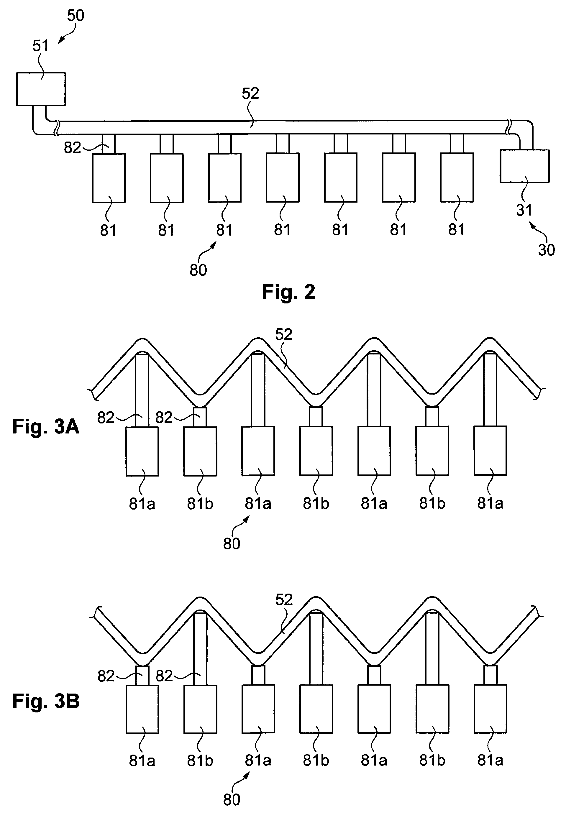
[0009]According to the present aspect, differences in elevation are formed by changing the shape of the ink supply path using the shape changing section. Then, sedimentation components which are included in the ink are moved from a high location to a low location. Due to this, it is possible to eliminate sedimentation which occurs inside the ink supply path by stirring the ink. In addition, it is possible to prevent sedimentation inside the ink supply path by changing the shape of the ink supply path before there is sedimentation of the components which are included in the ink inside the ink supply path.
[0011]According to the present aspect, differences in elevation are formed by pressing down the ink supply path. Due to this, it is possible to eliminate sedimentation.
[0013]According to the present aspect, it is possible to easily create differences in elevation in the ink supply path by driving the plurality of solenoids which are arranged along the ink supply path.
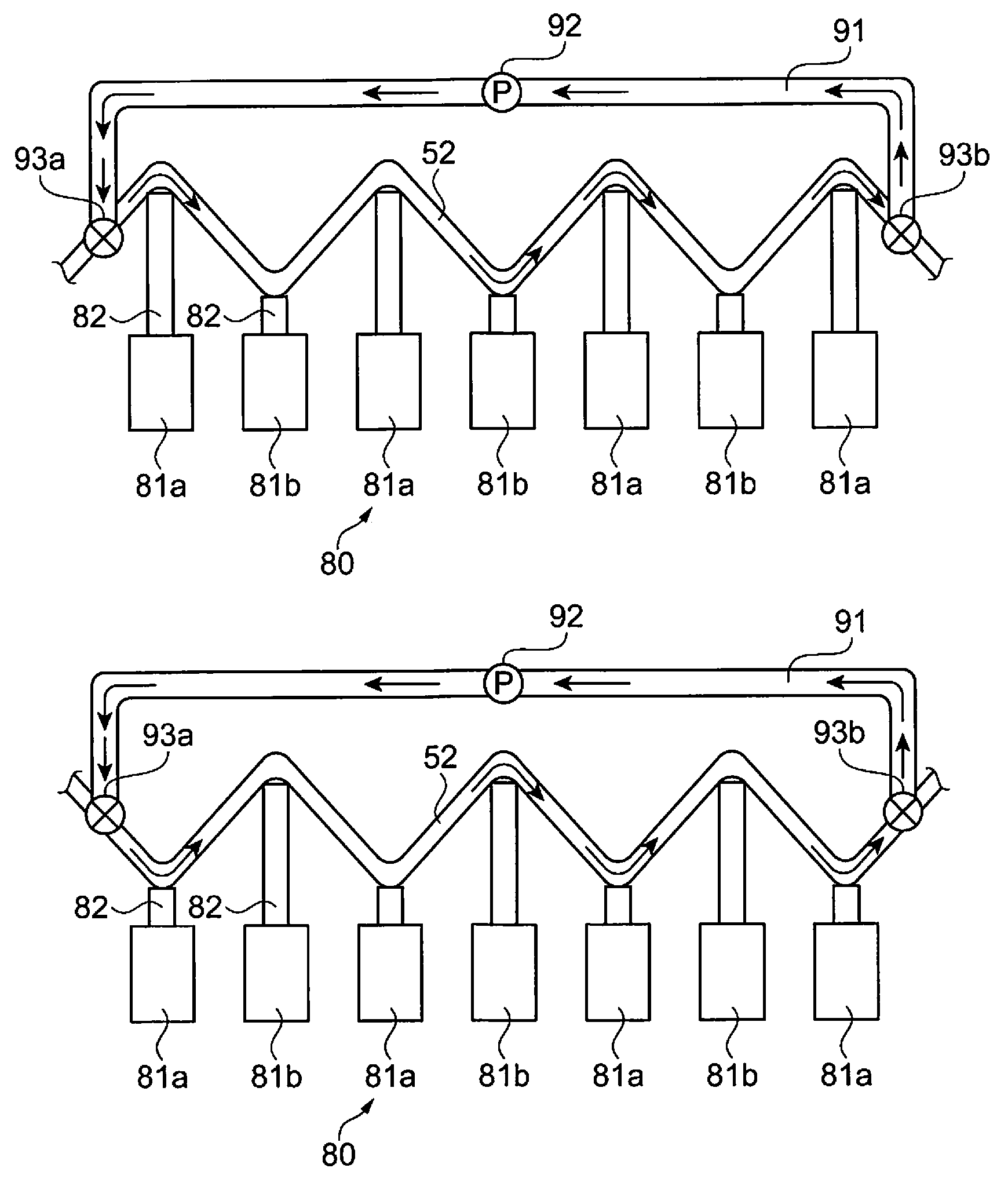
[0017]According to the present aspect, since the ink is circulated in the ink supply path and the bypass flow path, a stirring removal effect is improved and it is possible to shorten the time for sedimentation elimination.

Problems solved by technology

However, in a case where the flow path unit described above is applied to, for example, an industrial printing apparatus, there is a problem in that a long time is required to perform sediment removal by circulating the ink inside the flow path tube since the flow path tube which is arranged in the horizontal direction is comparatively long.

Method used


Image

  • Liquid droplet discharging apparatus
  • Liquid droplet discharging apparatus
  • Liquid droplet discharging apparatus

Examples


first embodiment

[0029]Firstly, a configuration of a liquid droplet discharging apparatus according to the first embodiment will be described. The liquid droplet discharging apparatus is provided with an ink tank which retains ink, a head which discharges the ink, an ink supply path which supplies the ink from the ink tank to the head, and a shape changing section which changes the shape of the ink supply path such that differences in elevation are formed in the direction of gravity in the ink supply path. Below, description will be given in detail.

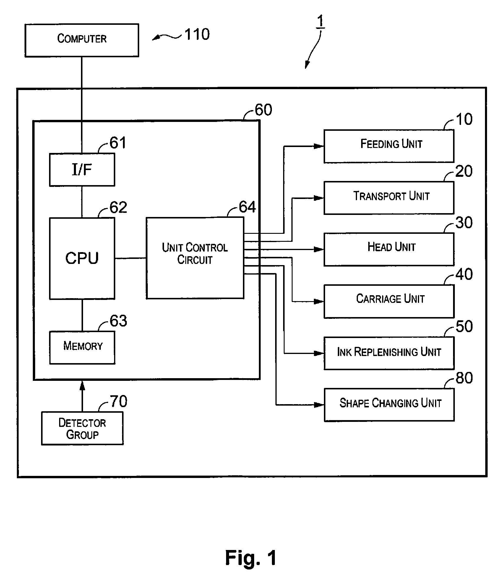
[0030]FIG. 1 is a block diagram illustrating a configuration of the liquid droplet discharge apparatus according to the present embodiment. In addition, FIG. 2 is a schematic diagram illustrating a configuration of the shape changing unit according to the present embodiment. A liquid droplet discharging apparatus 1 is, for example, an ink jet printer, and performs printing onto a printing medium by discharging ink from a head which will be described later...

second embodiment

[0045]Next, a configuration of a liquid droplet discharging apparatus according to the second embodiment will be described. FIG. 4 is a block diagram illustrating a configuration of the liquid droplet discharge apparatus according to the present embodiment. A liquid droplet discharging apparatus 1a according to the present embodiment is further provided with a circulation unit 90 in addition to the configuration of the liquid droplet discharging apparatus 1 according to the first embodiment described above. Below, description will be given in detail. Here, description of the configuration according to the first embodiment will be omitted.

[0046]The circulation unit 90 circulates the ink in the flow path which includes the ink supply path 52. FIG. 5 is a schematic diagram illustrating configurations of the shape changing unit and the circulation unit according to the present embodiment. The shape changing unit 80 includes the plurality of solenoids 81 and the solenoids 81 are arranged...

modified example 1

[0056]In the first and second embodiments described above, the plurality of solenoids 81a and solenoids 81b are alternately arranged along the ink supply path 52 and the solenoids 81a and the solenoids 81b are alternately driven, but the present invention is not limited to this. For example, the arrangement of the plurality of solenoids 81a and 81b may be changed, and furthermore, the driving method may also be changed. FIG. 7 is a schematic diagram illustrating a configuration of a shape changing unit according to modified example 1. As shown in FIG. 7A, the solenoids 81a and the solenoids 81b are arranged so as to face each other via the ink supply path 52. In addition, the solenoids 80b are arranged at positions which correspond to between two of the solenoids 80a which are adjacent to each other. Then, the solenoids 81a and 81b are driven at the same timing. Due to this, differences in elevation are formed with regard to the ink supply path 52 as shown in FIG. 7B. Also in this m...


PUM


Abstract

A liquid droplet discharging apparatus includes an ink tank configured to retain ink, a head configured to discharge the ink, an ink supply path configured to supply the ink from the ink tank to the head, and a shape changing section configured to change a shape of the ink supply path such that differences in elevation are formed in a direction of gravity in the ink supply path.

Description

CROSS-REFERENCE TO RELATED APPLICATIONS[0001]This application claims priority to Japanese Patent Application No. 2012-271118 filed on Dec. 12, 2012. The entire disclosure of Japanese Patent Application No. 2012-271118 is hereby incorporated herein by reference.BACKGROUND[0002]1. Technical Field[0003]The present invention relates to a liquid droplet discharging apparatus.[0004]2. Related Art[0005]In the prior art, techniques are known for eliminating sedimentation of components which are included in ink inside a flow path. For example, Japanese Unexamined Patent Application Publication No. 2012-152972 describes a flow path unit where discharging liquid is circulated inside a flow path tube by connecting a pump to the flow path tube which feeds ink in the horizontal direction and driving the pump.SUMMARY[0006]However, in a case where the flow path unit described above is applied to, for example, an industrial printing apparatus, there is a problem in that a long time is required to pe...

Claims


Application Information

Patent Timeline
Patent Type & Authority Patents(United States)
IPC IPC(8): B41J2/175B41J2/18
CPCB41J2/17596B41J2/175B41J2/18
Inventor MITSUO, NORITAKA
Owner SEIKO EPSON CORP
Learn More