Inverter device and air conditioner including the same
a technology of inverter device and air conditioner, which is applied in the direction of electronic commutator, dynamo-electric converter control, heating types, etc., can solve the problems of increasing the price of non-si transistors more expensive than si semiconductor elements, and the increase of the price of driving control circuits
- Summary
- Abstract
- Description
- Claims
- Application Information
AI Technical Summary
Benefits of technology
Problems solved by technology
Method used
Image
Examples
first embodiment
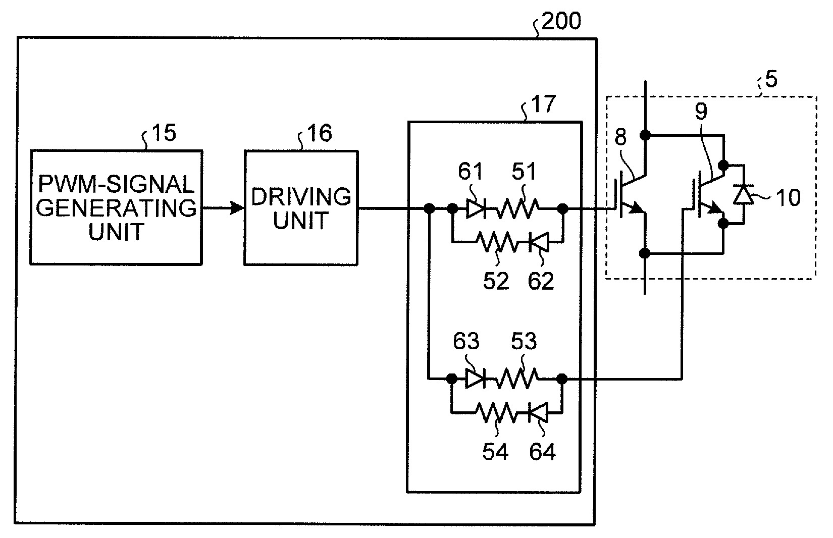
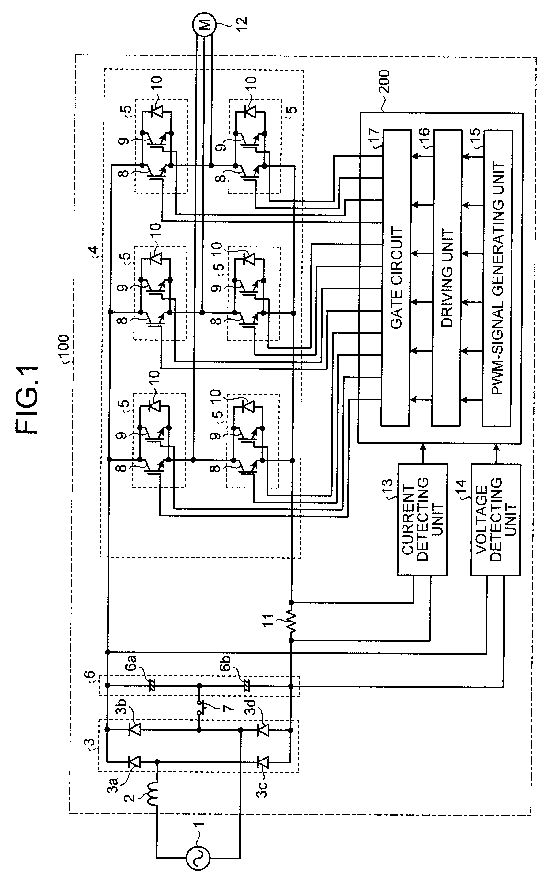
[0016]FIG. 1 is a diagram of a configuration example of an inverter device according to a first embodiment. As shown in FIG. 1, an inverter device 100 according to the first embodiment includes a reactor 2 for power factor improvement, a diode bridge (a rectifying circuit) 3 that rectifies an alternating-current voltage output from an alternating-current power supply 1 via the reactor 2, a smoothing capacitor 6 that smoothes a direct-current voltage rectified by the diode bridge 3, a converting circuit 4 that converts the direct-current voltage smoothed by the smoothing capacitor 6 into a desired alternating-current voltage, a current detecting unit 13 that detects an electric current flowing to a resistor 11 to thereby detect a circuit current flowing to the converting circuit 4, a voltage detecting unit 14 that detects a voltage across both ends of the smoothing capacitor 6 to thereby detect a direct-current voltage applied to the converting circuit 4, and a control unit 200 that ...
second embodiment
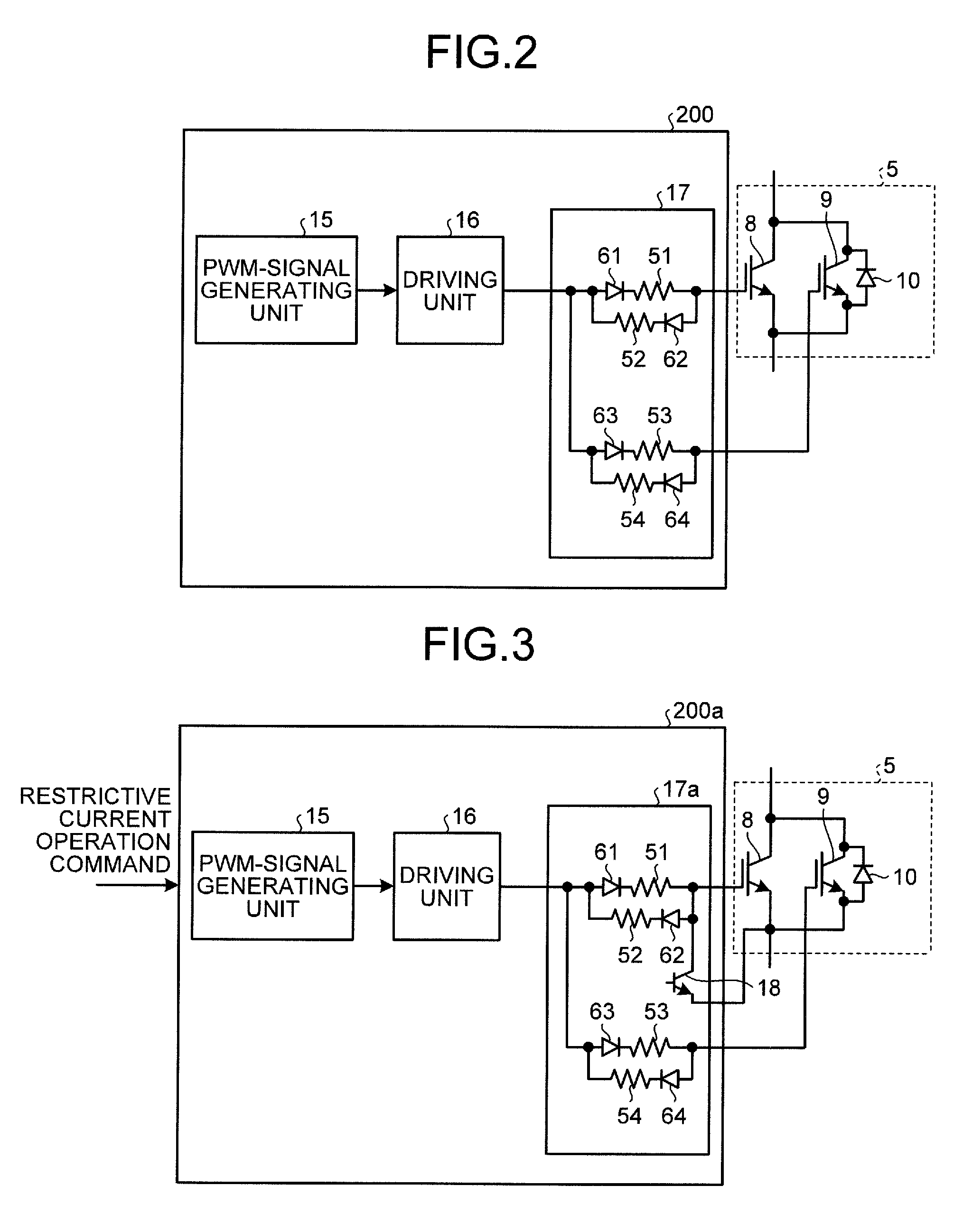
[0035]In an example explained in a second embodiment, only a second switching element including a WBG semiconductor is turned on and off in a low-load state. The low-load state means, for example, a state in which a compressor motor is actuated with a low load different from a load during a normal operation of the compressor motor, for example, when a dormant refrigerant in the compressor motor under suspension is prevented by restrictively energizing a motor winding to prevent the compressor motor connected as a load of a converting circuit from rotating.
[0036]FIG. 3 is a diagram of a configuration example of a gate circuit in an inverter device according to the second embodiment. An overall configuration of the inverter device 100 according to the second embodiment is the same as that of the inverter device according to the first embodiment. Therefore, components same as or equivalent to those in the first embodiment are denoted by the same reference numerals and signs and detaile...
third embodiment
[0044]In an example explained in a third embodiment, the inverter device explained in the first and second embodiments is applied to an air conditioner. FIG. 4 is a configuration schematic diagram of an outdoor unit of the air conditioner according to the third embodiment.
[0045]As shown in FIG. 4, an outdoor unit 30 of the air conditioner according to the third embodiment includes a fan 31 for facilitating heat exchange between an outdoor heat exchanger (not shown in the figure) and the outdoor air, a compressor 32 that circulates a compressed refrigerant to a refrigerant circuit (not shown in the figure) in the air conditioner, and the inverter device 100 according to the first or second embodiment.
[0046]In the example shown in FIG. 4, the inverter device 100 is set in an upper part of the outdoor unit 30. The inverter device 100 controls a rotational operation of a compressor motor included in the compressor 32. The inverter device 100 is not limited to be used for the control of ...
PUM
 Abstract
Description
Claims
Application Information
 - R&D
- Intellectual Property
- Life Sciences
- Materials
- Tech Scout
- Unparalleled Data Quality
- Higher Quality Content
- 60% Fewer Hallucinations
Browse by: Latest US Patents, China's latest patents, Technical Efficacy Thesaurus, Application Domain, Technology Topic, Popular Technical Reports.
© 2025 PatSnap. All rights reserved.Legal|Privacy policy|Modern Slavery Act Transparency Statement|Sitemap|About US| Contact US: help@patsnap.com


