
Enclosure system and method for facilitating installation of electrical equipment

a technology for enclosures and electrical equipment, applied in the direction of transformers/reacts, non-enclosed substations, substations, etc., can solve the problem of increasing the risk of accidents

Active Publication Date: 2014-11-18
HUBBELL INC
View PDF4 Cites 6 Cited by
  • Summary
  • Abstract
  • Description
  • Claims
  • Application Information

AI Technical Summary

Benefits of technology

This patent text describes an enclosure for electrical equipment that includes a frame, a first plate, and a first member. The first plate is moveable between a first position and a second position, and is at least partially supported by the first member when in the first position. This design allows for easy installation and replacement of a transformer in the enclosure. The technical effects of this patent include improved stability and safety during transportation and installation of electrical equipment, as well as increased efficiency and flexibility for transformer replacement.

Problems solved by technology

One continuing challenge in the field of metering transformer enclosures is in installation and replacement of transformers.
Inserting lifting equipment into an enclosure can increase the risk of accidents.

Method used


Image

  • Enclosure system and method for facilitating installation of electrical equipment
  • Enclosure system and method for facilitating installation of electrical equipment
  • Enclosure system and method for facilitating installation of electrical equipment

Examples


Embodiment Construction

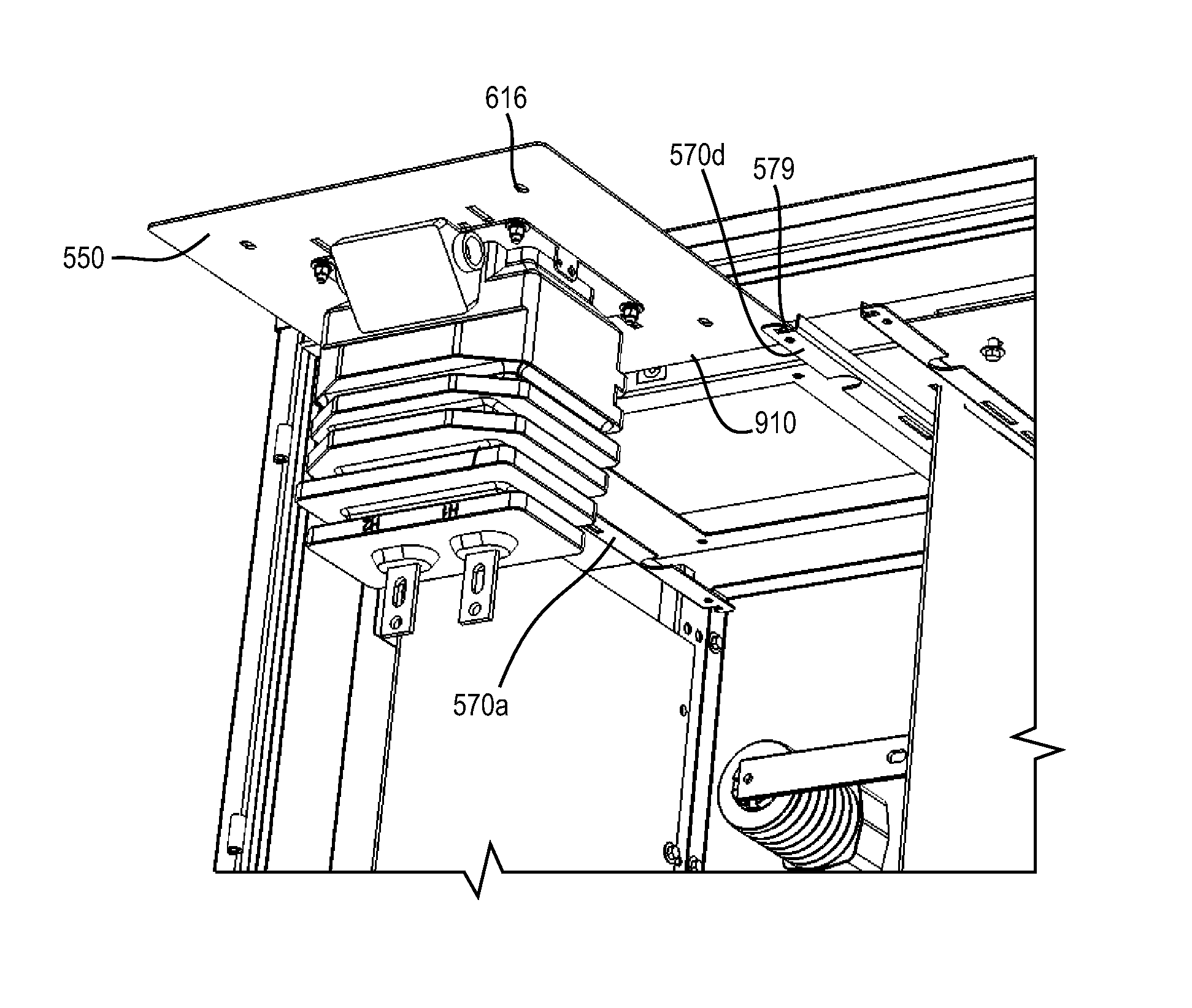
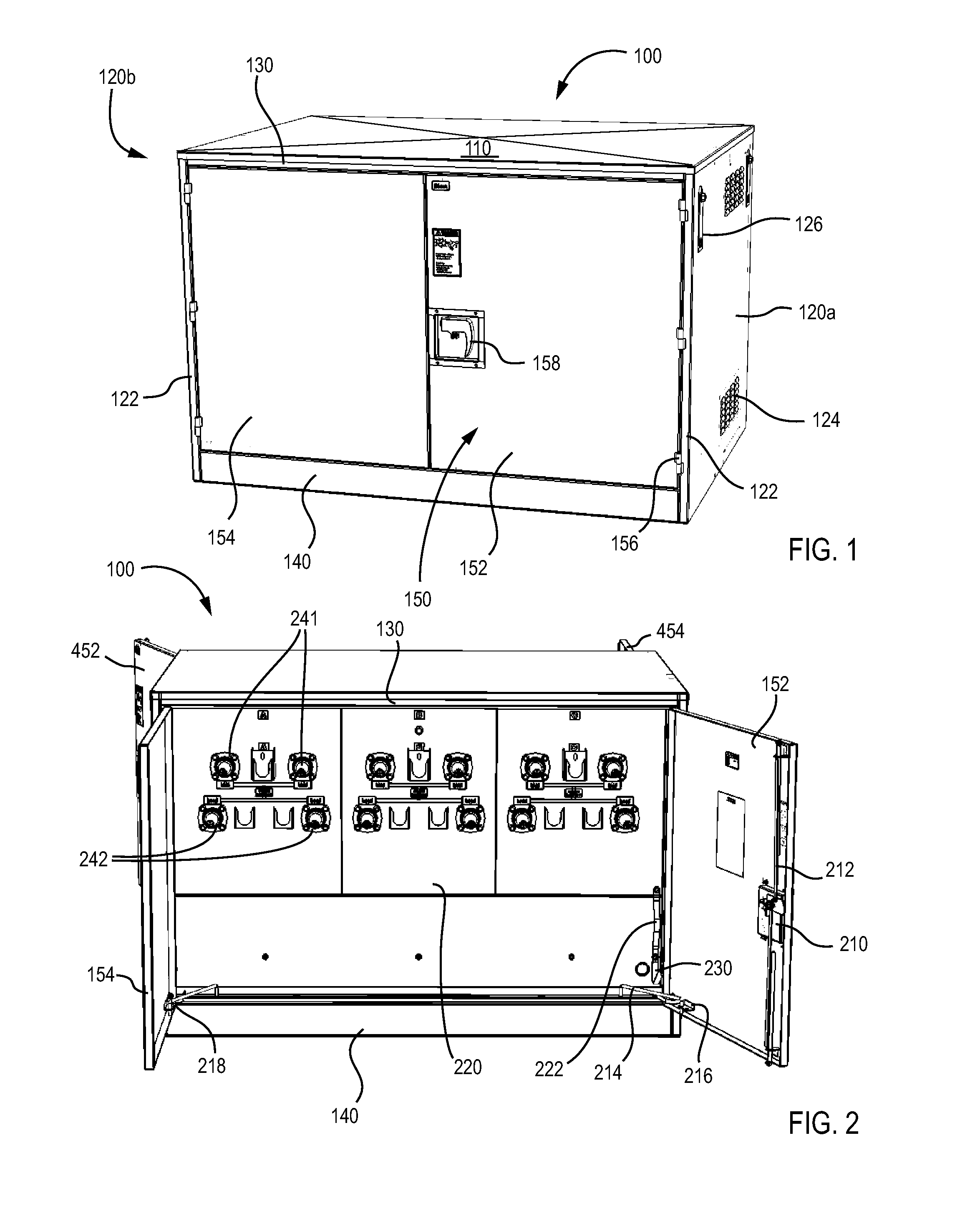
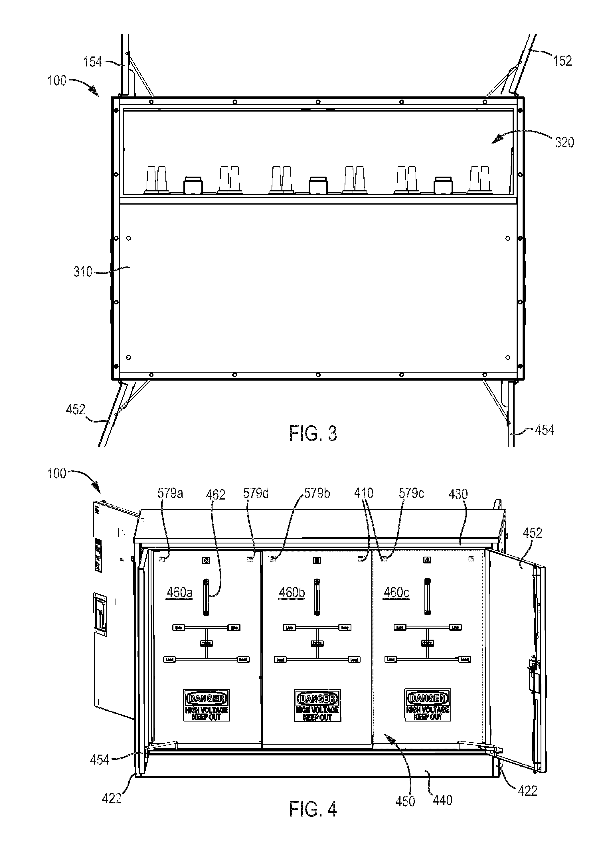
[0020]Referring to the FIGURES, an enclosure for electrical equipment and components thereof are shown according to exemplary embodiments. The enclosure generally includes a frame, a first plate, and a first member. The first member is coupled to the frame and configured to receive the first plate. The first plate may be configured to receive a transformer and may be movable between a first position and a second position. The first plate is at least partially supported by the first member when the first plate is in the first position. The first plate is offset from the first member when the first plate is in the second position.

[0021]According to an exemplary embodiment, the enclosure is used in electrical applications, such as, for metering of electric power. As such, the enclosure may be located in an industrial or commercial environment or residential neighborhood and receive electrical cables from a utility company. In this application, the enclosure may receive and provide sign...


PUM

PropertyMeasurementUnit
weightaaaaaaaaaa
electric poweraaaaaaaaaa
poweraaaaaaaaaa

Abstract

An enclosure for electrical equipment is provided. The enclosure includes a frame, a first plate, and a first member coupled to the frame and configured to receive the first plate. The first plate is configured to receive a transformer, movable between a first position and a second position, at least partially supported by the first member when the first plate is in the first position, and offset from the first member when the first plate is in the second position.

Description

BACKGROUND OF THE INVENTION[0001]The present disclosure relates generally to the field of enclosures for an electrical system. More specifically, the present disclosure relates to the field of enclosures suitable for metering and instrumentation transformers for power distribution.[0002]Enclosures are structures which separate contents from the surrounding environment. Some enclosures contain electrical or electronic equipment. These enclosures may provide for mounting of the electrical or electronic equipment, for preventing electrical shock to equipment users, and for protecting the equipment from the environment.[0003]One application for electrical enclosures is to house transformers for metering and instrumentation applications. In such an application, the enclosure may be located in an industrial or commercial environment or residential neighborhood and receive “line” electrical cables from a utility power company. The enclosure may also receive “load” electrical cables from th...

Claims


Application Information

Patent Timeline
Patent Type & Authority Patents(United States)
IPC IPC(8): H02B7/00H02B1/50A47G29/02A47B81/00H02B1/00E06B7/28H01F27/02H01F27/06H02B5/00A47B97/00A47F5/00A47B88/06E04G3/20A47B95/00H02B1/26A47B88/48
CPCH01F27/02H01F27/06H02B1/50H01F41/00H02B1/16H02B1/301H02B1/32Y10T29/49002Y10T29/4902
Inventor GEROVAC, JOSEPH, P.
Owner HUBBELL INC
Learn More