Split magnet loudspeaker

a loudspeaker and magnet technology, applied in the field of loudspeakers, can solve the problems of increasing the risk of reducing the efficiency of the loudspeaker, increasing the risk of distortion and unsatisfactory performance, and large mass, so as to improve the performance characteristics, reduce the weight package, and improve the effect of performan

Active Publication Date: 2014-11-18
HARMAN INT IND INC
View PDF25 Cites 10 Cited by
  • Summary
  • Abstract
  • Description
  • Claims
  • Application Information

AI Technical Summary

Benefits of technology

[0007]In another example, a bucking magnet assembly can be positioned relative to a magnet structure so that a greater portion of the magnetic flux generated by the magnet structure is contained within the voice coil gap. The bucking magnet assembly can improve the accuracy of voice coil movement and the overall performance of the loudspeaker. The bucking magnet assembly can have a bucking core coupled to split multiple magnets. A first and second bucking magnets can be positioned so that a polarity may be aligned in a same direction. The polarity of the first and second bucking magnets can be opposite to a polarity of the magnet structure. The bucking magnet assembly with the first and second bucking magnets may push the fringe field of the top of the bucking magnet assembly above the voice coil travel range, and can reduce stray magnetic fields.

Problems solved by technology

However, using a single thick magnet supported by a magnetically conductive pedestal may result in significant fringe magnetic fields that can increase the risk of reducing the efficiency of the loudspeaker.
For example, a BL that is non-linear and variable can cause an increased risk of distortion and unsatisfactory performance.
Moreover, using a single thick magnet supported by a magnetically conductive pedestal may result in a larger mass loudspeaker which can increase the manufacturing and shipping costs of the loudspeaker.

Method used


Image

  • Split magnet loudspeaker
  • Split magnet loudspeaker
  • Split magnet loudspeaker

Examples


Embodiment Construction

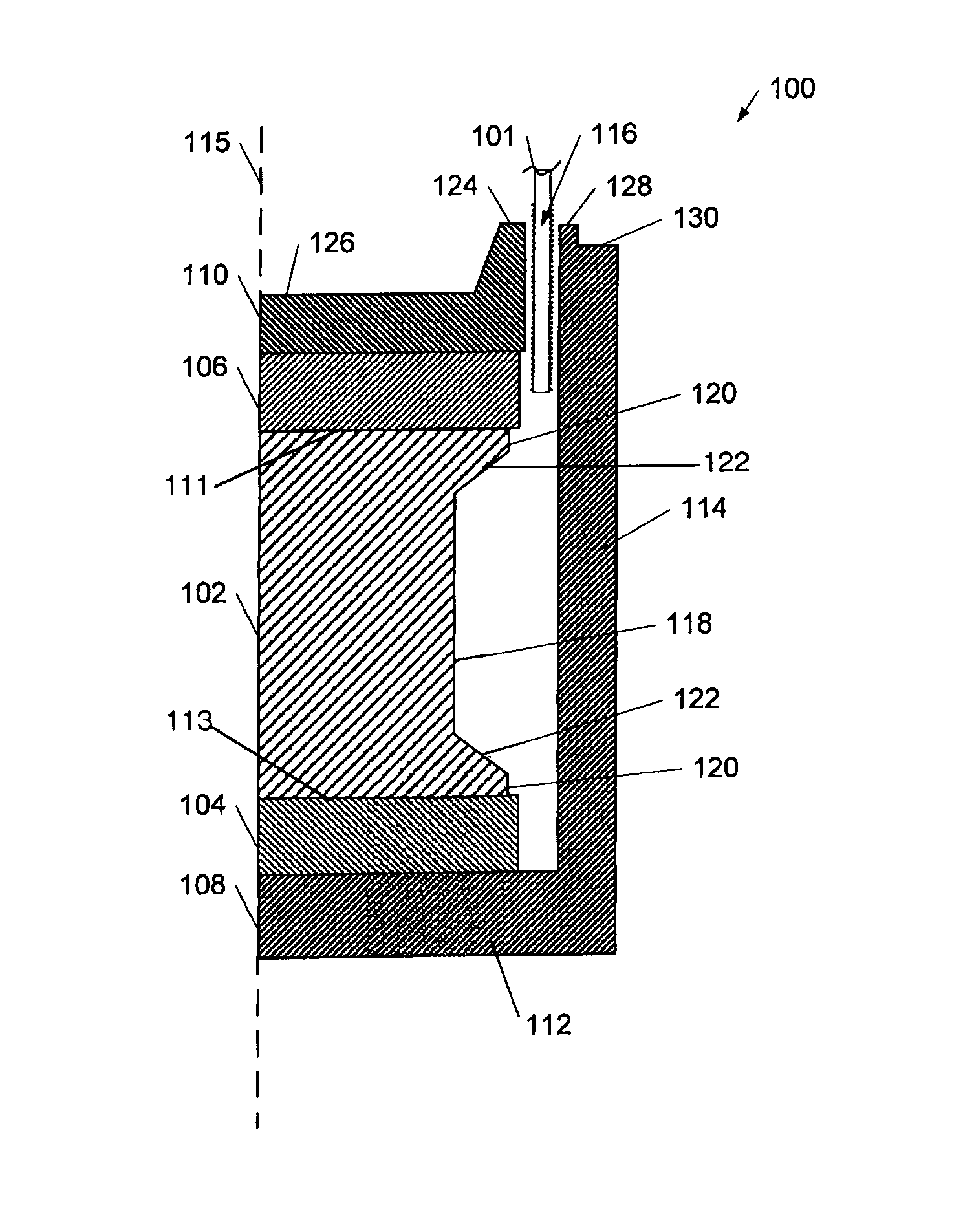
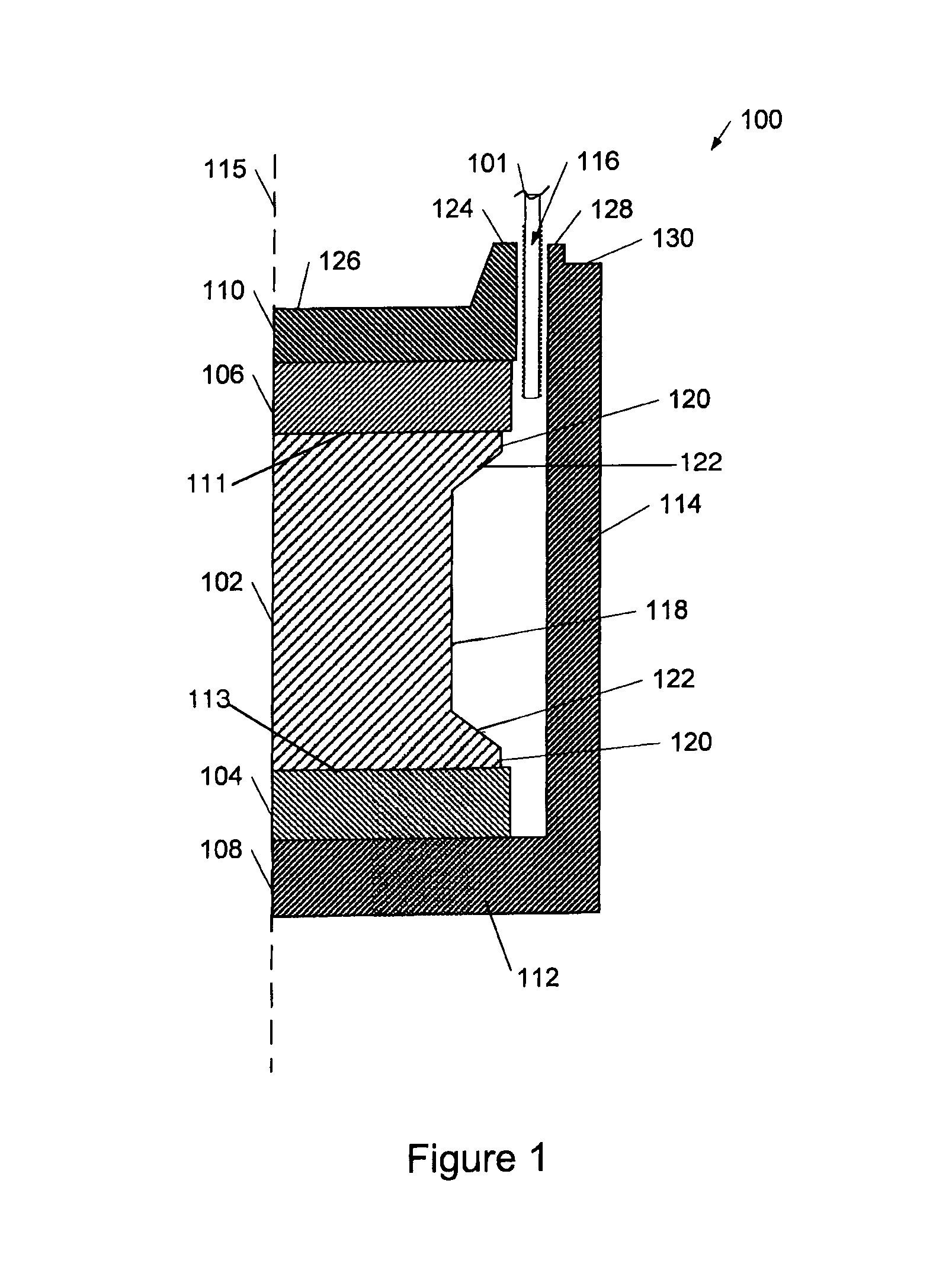
[0018]FIG. 1 illustrates a first example of a cross-section of a portion of a magnet structure 100 for a loudspeaker with a voice coil 101. The magnet structure 100 may include a core 102, a first magnet 104, a second magnet 106, a magnet housing 108, and a core cap 110. The magnet housing 108, also called a shell pot, may include a base 112 and an extension 114. The base 112 of the magnet housing 108 can be coupled to the first magnet 104 and can extend substantially perpendicular to a central axis 115 of the magnet structure 100. The extension 114 of the magnet housing 108 can extend generally in the same direction as the central axis 115, and may even be substantially parallel to the central axis 115. When the magnet structure includes the first and second magnets 104, 106, the magnets can be polarized in the same direction.

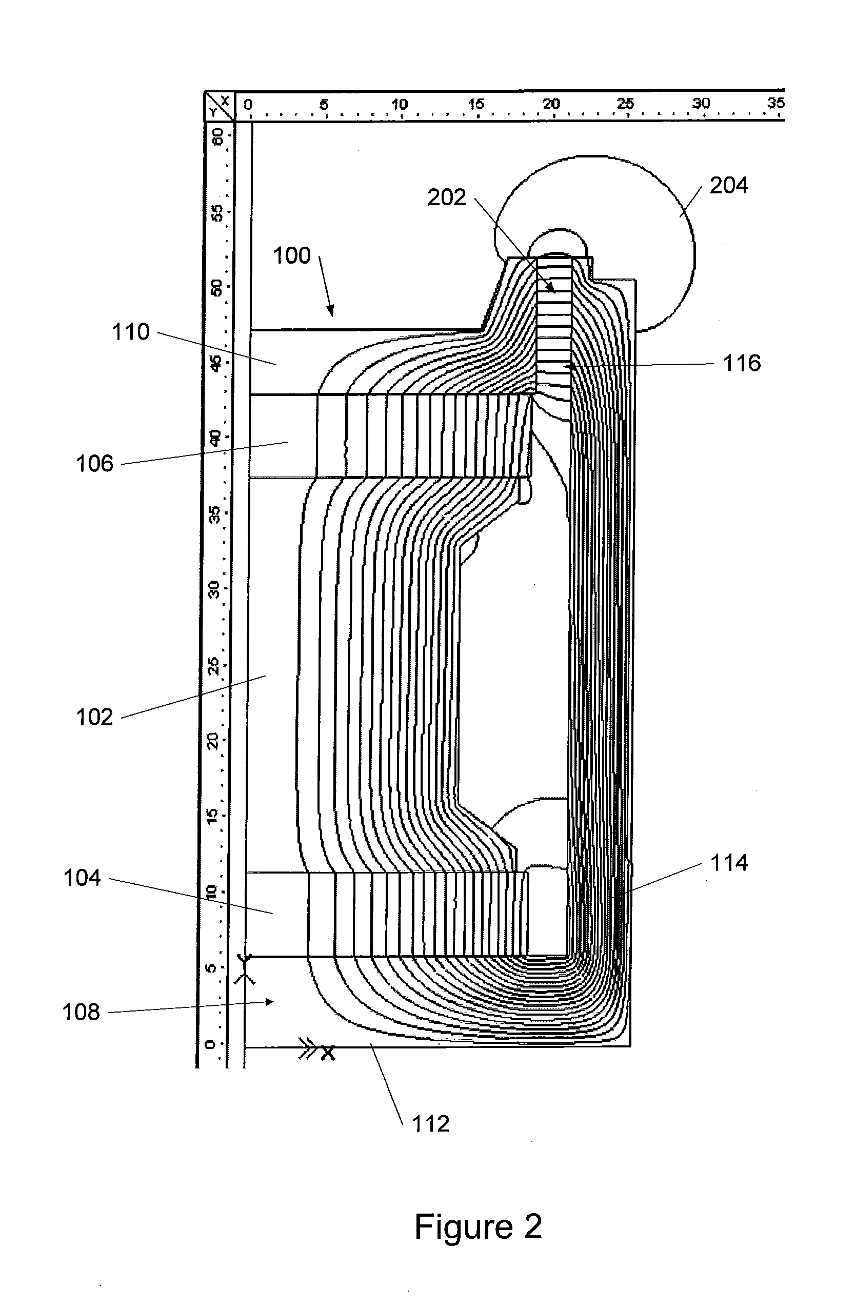
[0019]When the magnets 104, 106 are polarized in the same direction, the magnets may both contribute to a combined magnetic flux of the magnet structure 100. ...


PUM

PropertyMeasurementUnit
distanceaaaaaaaaaa
magnetic flux densityaaaaaaaaaa

Abstract

A loudspeaker can provide magnetic flux from polarity-aligned split magnets to drive voice coils and generate sound. The loudspeaker may have reduced stray magnetic fields and a BL curve with symmetric and linear characteristics. The loudspeaker can include a core, split magnets, a magnet housing, a core cap, and a voice coil gap formed between the magnet housing and the core cap. Magnetic flux produced by the split magnets may be combined, directed, and / or concentrated by the core cap and magnet housing within the voice coil gap. At least portions of a voice coil may be positioned within the voice coil gap and a diaphragm may be coupled to the voice coil. A bucking magnet assembly may contain a magnetic flux of the magnet structure to further improve performance. The bucking magnet assembly may include split magnets with an aligned polarity that is opposite the polarity of the magnet structure.

Description

BACKGROUND OF THE INVENTION[0001]1. Technical Field[0002]The invention relates to loudspeakers, and in particular, to loudspeakers with split multiple magnets having polarities aligned in the same direction.[0003]2. Related Art[0004]Loudspeakers convert electrical energy into sound and typically include a diaphragm, a magnet structure, and a voice coil. The magnet structure may include one or more magnets and a core cap. The core cap can direct and concentrate a magnetic flux produced by the magnets into a voice coil gap. The voice coil can be connected to the diaphragm and positioned in the voice coil gap. When electrical energy flows into the voice coil, an induced magnetic field can be created that interacts with the magnetic flux in the voice coil gap. The voice coil may carry a current in a direction substantially perpendicular to the direction of the magnetic flux produced by the magnet structure, so that the interaction between the voice coil current and the magnetic flux can...

Claims


Application Information

Patent Timeline
Patent Type & Authority Patents(United States)
IPC IPC(8): H04R9/02B23P11/00H04R1/00
CPCH04R9/025H04R2209/022Y10T29/49826H04R9/02H04R9/06
Inventor DANOVI, BENNY
Owner HARMAN INT IND INC
Why Eureka
Try Eureka