
Ergonomic dental flossing device

a dental flossing and ergonomic technology, applied in the field of dental flossing devices, can solve the problems of difficult operation, inability to secure the bow on the handle, and other bow-type devices with the appropriate means, etc., and achieve the effect of convenient adjustment of tension, convenient adjustment of ergonomic structure, and convenient adjustment of position

Active Publication Date: 2014-11-25
VERIFRESH
View PDF21 Cites 8 Cited by
  • Summary
  • Abstract
  • Description
  • Claims
  • Application Information

AI Technical Summary

Benefits of technology

The present invention is a new flossing device with an optimized structure and adjustable tension for optimal cleaning. The floss holder has a special geometry that allows adjustment only when needed, reducing the risk of injury to the delicate tissue of the gums. The device also has improved ergonomics, safety standards, and cleaning efficiency.

Problems solved by technology

The above-mentioned flossing devices do not satisfactorily fulfill their task.
The known manually operated bow-type flossers, because they have the dental floss either aligned or perpendicular with the handle, are difficult to operate when trying to clean the back teeth or front teeth because of the inappropriate orientation of the floss string.
Other bow-type devices do not have the appropriate means for securing the bow on the handle.
Another shortcoming of all of these prior art bow-type flossers is that the tension in the flossing string is fixed, so that the relatively high tension required to enable proper insertion of the floss between the teeth, which action requires the floss to remain tense, does not allow the floss to curve around the profile of the teeth away from the interdental space.
As a consequence, proper cleaning of plaque and bacteria from surfaces of the teeth other than interdental surfaces is not readily performed.
Furthermore, the high tension of the floss in prior art flossers presents a danger of easily wounding the delicate tissue of the gums when attempting to clean surfaces of the teeth other than the interdental spaces.

Method used


Image

  • Ergonomic dental flossing device
  • Ergonomic dental flossing device
  • Ergonomic dental flossing device

Examples


Embodiment Construction

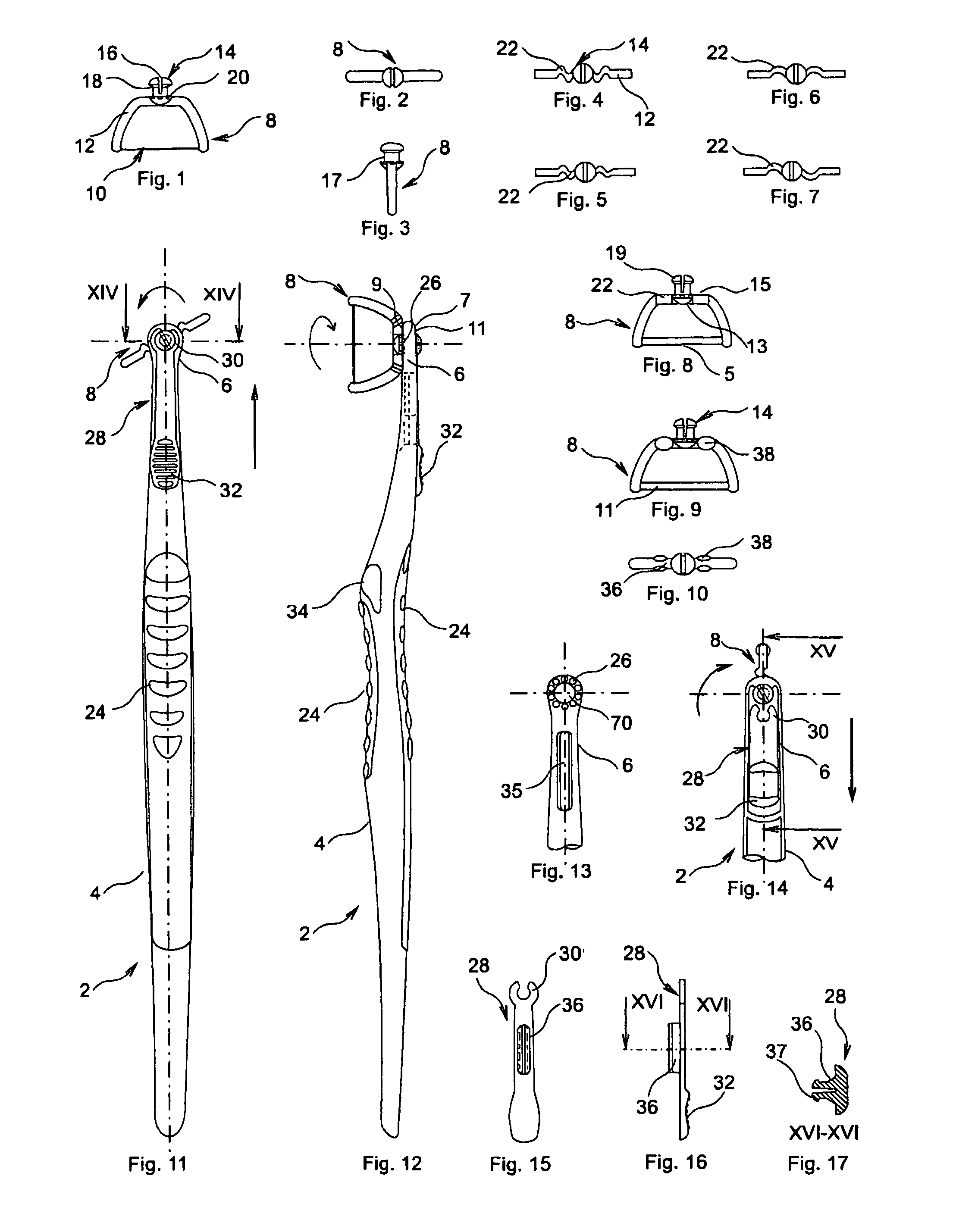
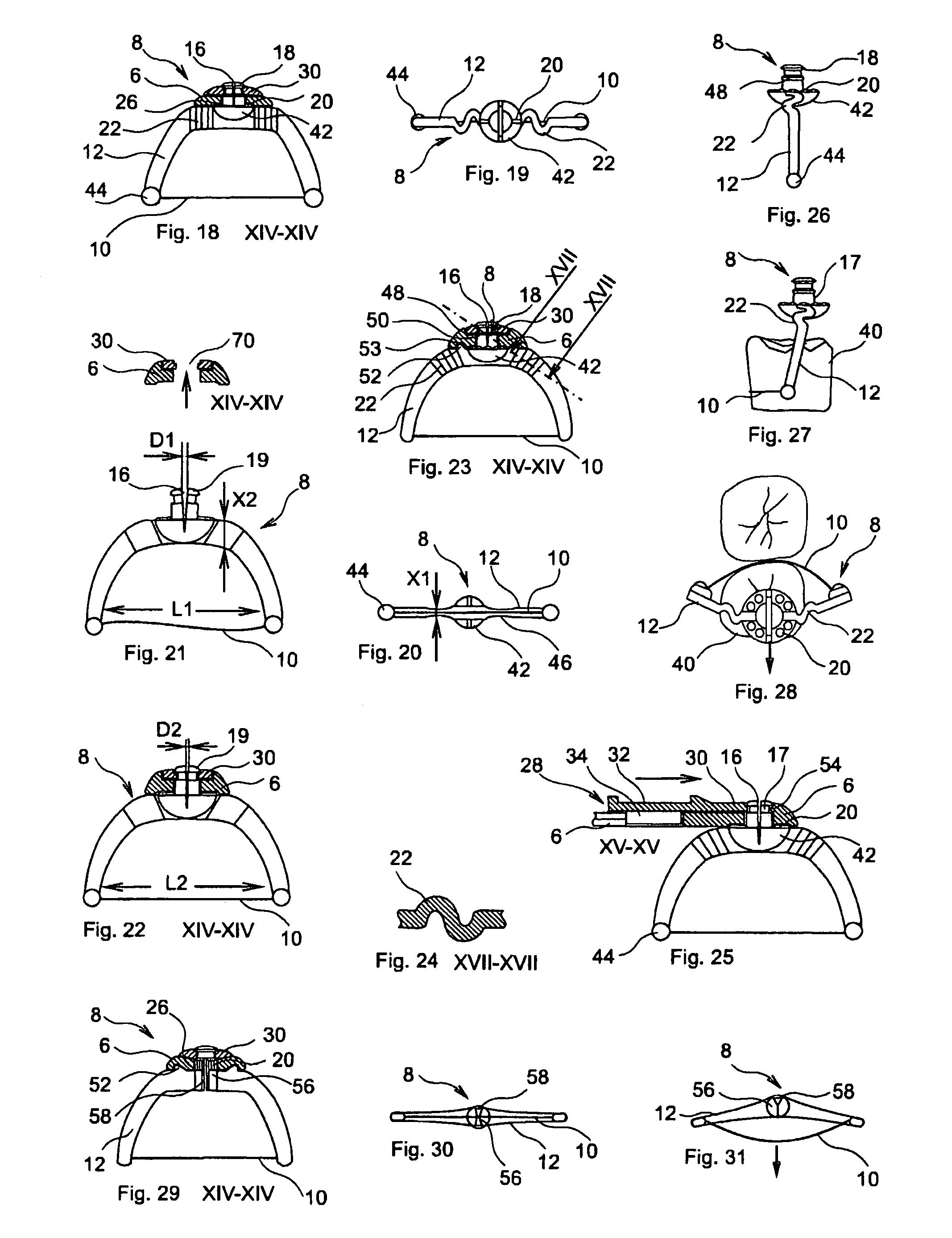
[0089]Referring now to the drawings, there is illustrated in FIGS. 11, 12 and 13 a preferred embodiment of the flossing device, 2 according to the present invention.

[0090]The flossing device essentially comprises two parts: a head portion, 6 and a grasping means, 4, which may be made of any suitable material such as plastic, as an integral unit or as two separate, detachable inter-connectable units, rendering the head portion disposable after one or more uses. The finger grips, 24 on the grasping means can be made out of the same material as the grasping means or out of elastomer material. The sole purpose of the grasping means is to hold and manually move the head portion with the floss holder mounted on it in between the teeth, in a straight, and / or circular motion, while applying controlled pressure. Hence, while the most commonly used grasping means is embodied by a handle of any kind, including those of the type employed with a toothbrush, other types of handles or grasping mea...


PUM


Abstract

A dental flossing device comprising a handle and a floss holder. The floss holder comprises a base portion and a pair of spaced-apart arms accommodating dental floss therebetween. The floss holder has greater flexibility in a direction laterally perpendicular to the direction of the length of said length of dental floss than in the direction of the floss itself. This flexibility is provided either by incorporating at least one convoluted section into either the base portion or the pair of spaced-apart arms of the floss holder, or by providing either the base portion or the pair of spaced-apart arms with a reduced cross sectional dimension in the lateral direction generally perpendicular to the floss than in the direction generally parallel to the floss, or by means of a groove in the neck by which the floss holder is attached to the handle.

Description

RELATED APPLICATION[0001]This application claims the benefit of priority to PCT application No. PCT / IL2005 / 00124, filed Nov. 23, 2005, which in turn claims the benefit of priority to U.S. provisional applications No. 60 / 630,462 filed Nov. 24, 2004, and 60 / 670,275, filed Apr. 12, 2005. The above mentioned applications are incorporated herein by reference in their entirety.FIELD OF THE INVENTION[0002]The present invention relates to the field of dental flossing devices with adjustable floss holders, especially of types designed to provide cleaning of additional surfaces of the teeth, not limited to the interdental spaces.BACKGROUND OF THE INVENTION[0003]Flossing devices of various kinds are known in the art. For example, U.S. Utility Pat. No. 664,126 describes a simple floss holder aligned with the grasping means, U.S. Utility Pat. No. 5,483,982 shows a disposable floss holder bow perpendicular with the grasping means, and U.S. Utility Pat. No. 3,927,686 discloses a swiveling head dis...

Claims


Application Information

Patent Timeline
Patent Type & Authority Patents(United States)
IPC IPC(8): A61C15/00A46B5/00A61C15/04
CPCA46B2200/1066A61C15/046A46B5/0083A46B5/0075A46B2200/108A61C15/048A61C15/047
Inventor WELT, THEODOREWEISBERG, JONATHAN
Owner VERIFRESH
Learn More