
Electrical box, integrated flange and cover mechanisms

a technology of electrical outlets and mechanisms, applied in the direction of coupling device connections, transportation and packaging, packaging, etc., can solve the problems of current designs that cannot penetrate the commercial market, little of the patented derivatives finding any level of commercial appeal, and obtrusive aesthetic design, etc., and achieve the effect of saving energy

Inactive Publication Date: 2014-11-25
BATCHELOR THOMAS M
View PDF18 Cites 12 Cited by
  • Summary
  • Abstract
  • Description
  • Claims
  • Application Information

AI Technical Summary

Benefits of technology

The present invention is a multi-configured electrical box, integrated flange, and various cover mechanisms that can be independent of each other and combined in different ways. The invention aims to make electrical outlets invisible in new construction and remodeling, providing safety for children and energy savings. The flange covers the drywall cutout for the electrical box and protects from exposed wires in the outlet, seals the gap between electrical box and drywall from which energy is lost, and aligns with the cover when the cover is closed. When the outlet is in use, the cover remains attached to the unit and aligns with the closed cover for a seamless appearance. The invention is child-safe, energy-efficient, and easy to install.

Problems solved by technology

Despite the abundance of related art in this sector, practically all indoor electrical outlet boxes and covers sold in the United States are of traditional design, with little of the patented derivatives finding any level of commercial appeal.
The failure of current designs to penetrate the commercial market results from the following:i) In terms of safety: obtrusive aesthetic design, excessive manufacturing cost or difficulty in installation.
Safety features impede normal access to outlets in such a manner as to deter the housing developers from incorporating permanent inconveniences to a majority of customers on behalf of a minority of customers.
Also, the construction necessary to retrofit an outlet for this temporary purpose is cost prohibitive and impractical.
Therefore add-on temporary products such as plastic electrical outlet safety caps dominate the marketplace.ii) In terms of aesthetics, most designs, (a) amount to a derivative of a cap that protrudes from the wall, clearly visible and therefore creating limited appreciable aesthetic benefit, (b) incorporate covers that either require storage elsewhere when the outlet is in use or that are more obtrusive when the outlets are in use than cover-free outlets, (c) require excessive manufacturing cost, (d) require additional labor for the home and office contractors.iii) In terms of recessed outlet design, (a) too many electrical devices utilize low voltage transformers or other plugs that a recessed outlet will not accommodate, thereby preventing prevalent installation, (b) a recessed design that fails to incorporate aesthetic closures and easy closing mechanisms offers limited benefit outside of special applications.
As a result, installations of such designs are relegated to specialty uses such as wall-mounted audio visual equipment.
However, no other room in a home or office building offers such a means of obscuring the electrical outlets in a manner that would preserve the aesthetics of an un-breached wall.
The lack of commercial penetration by electrical boxes other than of standard design is evidence that no current design has incorporated the four necessary elements:(i) aesthetically appealing design,(ii) user-friendly mechanical operation that provides easy access to the outlet,(iii) competitive manufacturing cost, and / or(iv) the same field installation steps as used for standard boxes and covers.
As referenced in (iii) above, the parts used for mechanical operation and the general design as a whole cannot be significantly more expensive to manufacture than standard boxes and cover plates.
However, no prior art has produced designs of any one of these elements sufficient to penetrate the current marketplace with these individual attributes and particularly in combination with one another.

Method used


Image

  • Electrical box, integrated flange and cover mechanisms
  • Electrical box, integrated flange and cover mechanisms
  • Electrical box, integrated flange and cover mechanisms

Examples


embodiment 1

[0064

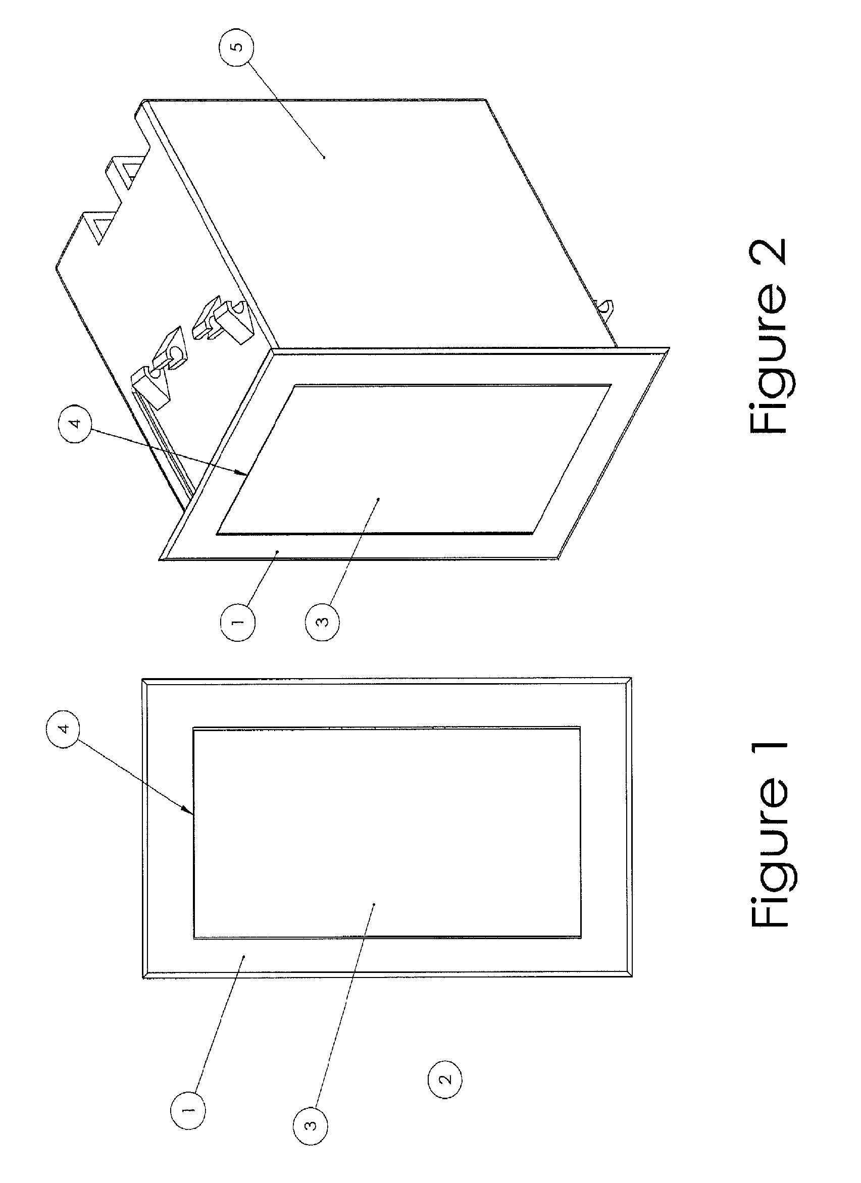
[0065]FIGS. 1 and 2 show the fully assembled unit, front and side view, installed with cover closed. The flange 1 surrounds and integrates the unit into the surrounding drywall 2. Cover 3 is closed with only the outline 4 of the intersection of the flange and cover being visible. The electrical box 5 shown in FIG. 2, which is an integral component of the present invention, is obscured in FIG. 1 and the electrical outlet is obscured in FIGS. 1 and 2.

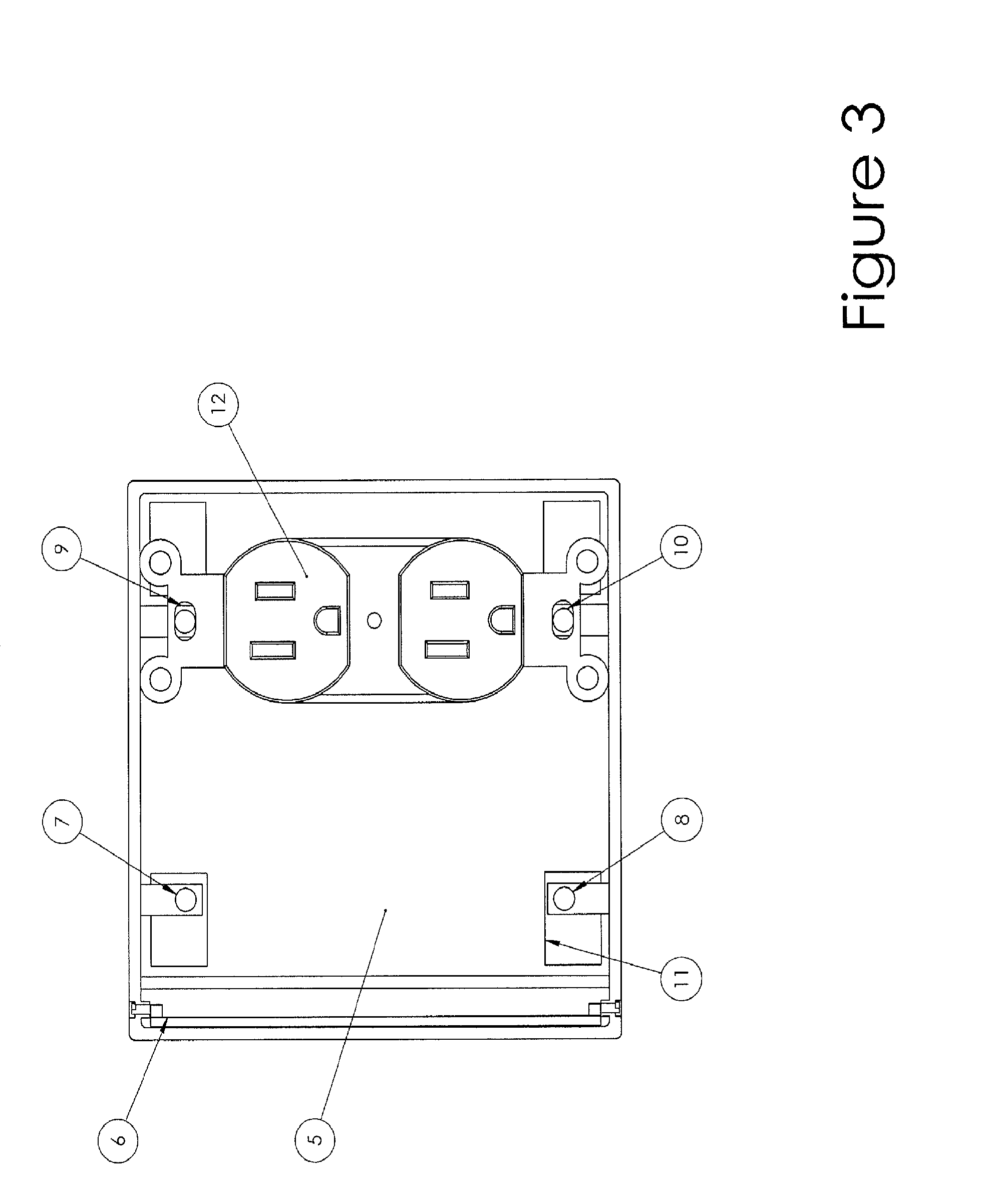
[0066]FIG. 3 shows the electrical box 5 having a height of 4.25″. The single cover is retracted into the open box and only the leading edge 6 of the cover is exposed.

[0067]Top mounting plates 7 and 9 and bottom mounting plates 8 and 10 include electric outlet stabilizing tabs 11. On standard electrical boxes, the stabilizing tabs of the outlet rest on the outside edge of the box and extend beyond the top and bottom of the box.

[0068]According to one example of this embodiment, top mounting plate 7 and bottom mounting plate 8 may be fo...

embodiment 2

[0080

[0081]FIG. 11 shows an electrical box according to a second embodiment of the present invention. The electrical box 5 in Embodiment 2 is substantially similar to the electrical box in Embodiment 1; however, the closure mechanism differs. The closure mechanism in Embodiment 2 is formed as dual tracks 27 and 28 built into the electrical box, in which a sectional door, attached to a roller, shall be inserted, much like a vertically operated garage door and track. This door (or cover) retracts into the electrical box, which is designed to accept the door due to the box width, internal hinge tracks, and interior box wall (not shown) that prevents interference from electrical wires inside the box, each more fully described under FIGS. 4. When combined with the cover configuration shown in FIG. 13, the electrical outlet is obscured when not in use. Tracks 29 and 30 would support a horizontal (close across) closure utilizing the closures shown in FIG. 15 or FIG. 16. Screw holes 31 and ...

embodiment 3

[0093

[0094]FIG. 19 shows Embodiment 3 of the closure mechanism incorporated into the electrical box 5. The electrical box 5 in Embodiment 3 is substantially similar to the electrical box in Embodiments 1 and 2; however, the closure mechanism differs. The top mounted hinge tracks 39 and bottom mounted hinge tracks 40 are built into the electrical box 5, can receive cover hinges shown in FIGS. 20 and 21, and are formed on only one side of the electrical box 5, rather than three sides in Embodiment 2.

[0095]Tracks 41 / 42, when combined with 39 / 40, can receive split side-by-side covers. Tracks 43 / 44 provide a single vertical (close down) cover configuration and when utilized with tracks 45 / 46 and a split vertical cover, a single outlet may be obscured while other outlet is in use.

[0096]The invented electrical box could accommodate all or any one of the above configurations.

[0097]FIGS. 20 and 21 show that Embodiment 3 is configured to integrate solid (non-sectional) covers attaching only a...


PUM


Abstract

A “no profile” electrical box, integrated flange / protective assembly and interchangeable cover that obscures standard electrical outlets such that a wall surface appears nearly continuous, uninterrupted by the outlet or cover when in use or not in use. The profile of the combined unit equals only the thickness of the material from which it is constructed; no hinges, screws or fasteners of any kind are visible and no part of the assembly requires detachment or storage when the outlet is in use, as the hinged cover is undetectably stored in the electrical box, or may be used to cover the electrical cords when engaged in the outlet. Exemplary embodiments of the cover obscure the electrical outlet. Together, the electrical box and flange assembly allow the electrical outlet to be flush mounted or recessed interchangeably, even after installation.

Description

BACKGROUND OF THE INVENTION[0001]1. Field of the Invention[0002]The present invention relates to mechanisms for mounting electrical outlets.[0003]2. Description of the Related Art[0004]Techniques for mounting and covering standard electrical outlets are innumerable. Most variations concern one of three themes, (i) safety for small children, (ii) aesthetics or (iii) recession for electrical cord management. Despite the abundance of related art in this sector, practically all indoor electrical outlet boxes and covers sold in the United States are of traditional design, with little of the patented derivatives finding any level of commercial appeal. The failure of current designs to penetrate the commercial market results from the following:[0005]i) In terms of safety: obtrusive aesthetic design, excessive manufacturing cost or difficulty in installation. Electrical outlet installation is generally permanent in nature, while children's safety is required only periodically and temporaril...

Claims


Application Information

Patent Timeline
Patent Type & Authority Patents(United States)
IPC IPC(8): H02G3/14H02G3/12
CPCH02G3/123H02G3/081H02G3/14H01R13/4532H01R13/447H02G3/088H02G3/12
Inventor BATCHELOR, THOMAS, M.
Owner BATCHELOR THOMAS M
Learn More