Remote jettison disconnect system for a mine roller

a technology of remote jettison and mine roller, which is applied in the field of remote jettison disconnect system of mine roller, to achieve the effect of reducing friction and wear

Inactive Publication Date: 2014-12-02
USA REPRESENTED BY THE SEC OF THE NAVY
View PDF5 Cites 2 Cited by
  • Summary
  • Abstract
  • Description
  • Claims
  • Application Information

AI Technical Summary

Benefits of technology

The technical effect of this patent is to provide a mechanism for releasing or keeping a lock in place by means of two shafts which can be controlled with an electric actuator. This allows for easy operation without requiring excessive force or effort. Additionally, there is no movement between the parts when the device is at rest, making it more stable and reliable.

Problems solved by technology

The technical problem addressed in this patent text relates to the need for an improved system that allows operators to safely release the Mine Rollers System (MRS) from tactical vehicles without being exposed to potential dangers caused by enemy fire.

Method used


Image

  • Remote jettison disconnect system for a mine roller
  • Remote jettison disconnect system for a mine roller
  • Remote jettison disconnect system for a mine roller

Examples


Embodiment Construction

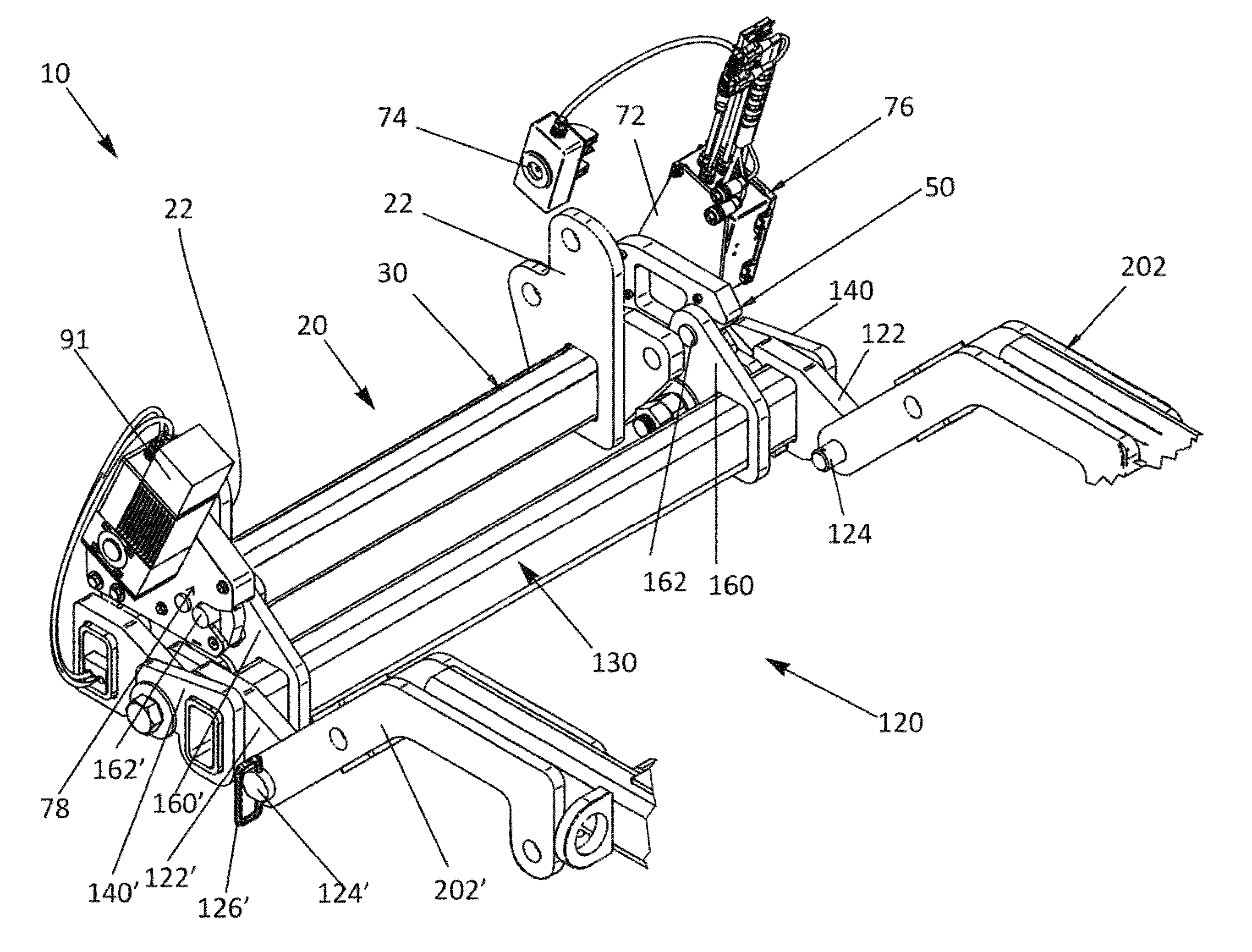
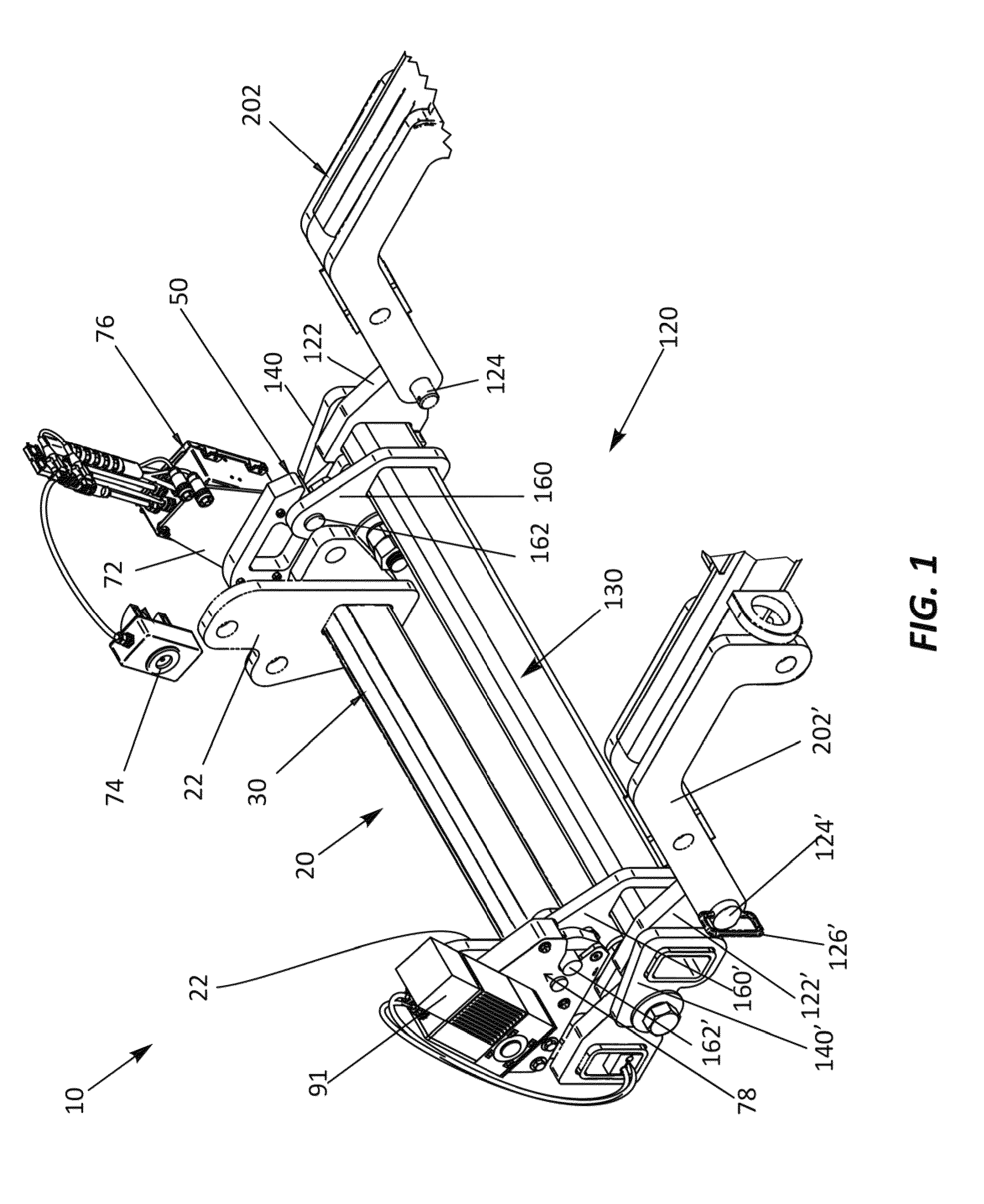
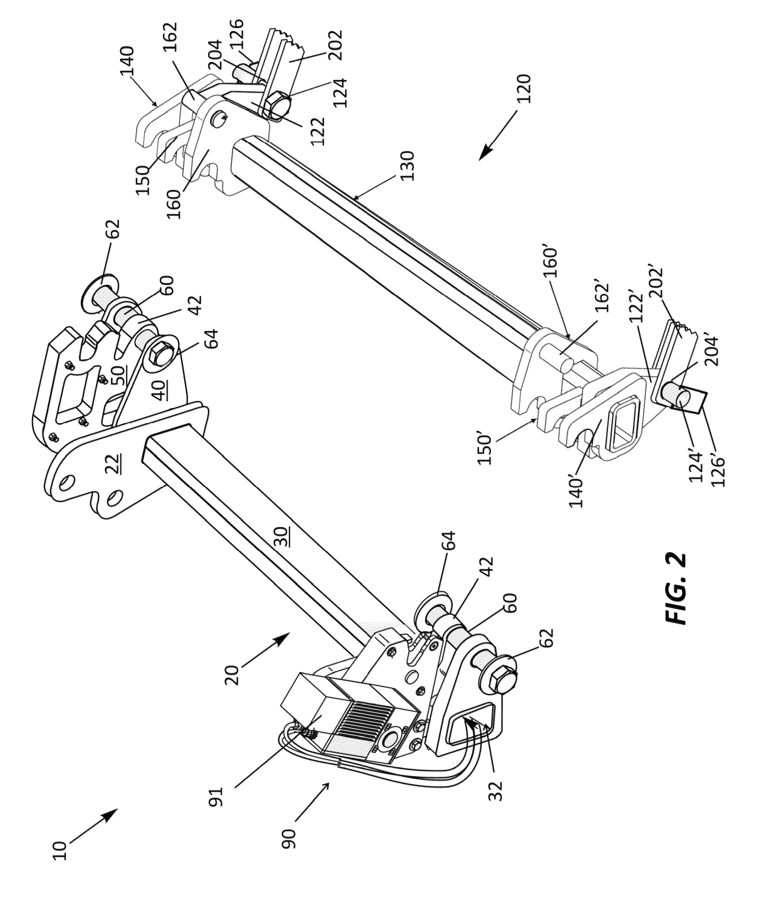
[0031]The invented remote jettison disconnect system (RJDS) provides in-cab release of a mine roller mounted to a tactical vehicle, thus eliminating the need for personnel to exit the vehicle and be exposed to hazardous conditions while disconnecting the mine roller. The system 10, as shown in FIG. 1, includes two assemblies: A tactical vehicle assembly 20 and a mine roller assembly 120. In FIG. 1 the assemblies 20,120 are connected. The tactical vehicle assembly 20 is shown in greater detail in FIG. 3. The tactical vehicle assembly 20 is mounted to a strength member front bumper 100 using at least two pairs of support brackets 102,104. Holes 106 are for head lamps (not shown). The illustrated support brackets are mounted on the front 102 and the bottom 104 of the front bumper 100, and are aligned to be mated to a pair of tactical vehicle mounting plates 22 on tactical vehicle assembly 20. Each tactical vehicle mounting plate 22 has an upper rear mounting hole 24 and lower rear moun...


PUM


Abstract

A remote jettison system is provided to disconnect a mine roller from a tactical vehicle. The system enables personnel conducting mine roller operations to disengage the vehicle from the mine roller without leaving the vehicle. The remote jettison system has two assemblies: A mine roller assembly and a tactical vehicle assembly. The mine roller assembly, which is connected to the mine roller, can be remotely disconnected from the tactical vehicle assembly, which is mounted on the vehicle. The system utilizes one mechanized latch to release the mine roller assembly from the tactical vehicle assembly, allowing the force of gravity to cause them to separate.

Description


Claims


Application Information

Patent Timeline
Owner USA REPRESENTED BY THE SEC OF THE NAVY
Why Eureka
Try Eureka