Aerodynamic skirts for land vehicles

a technology of aerodynamic skirts and land vehicles, applied in the direction of roofs, transportation and packaging, vehicle arrangements, etc., can solve the problems of increasing fuel consumption, reducing aerodynamic stability and driving safety, and airflow around the vehicle produces aerodynamic drag. , to achieve the effect of efficient reduction of aerodynamic drag

Active Publication Date: 2014-12-02
PRASKOVSKAYA ELEANOR +2
View PDF26 Cites 41 Cited by
  • Summary
  • Abstract
  • Description
  • Claims
  • Application Information

AI Technical Summary

Benefits of technology

The technical effect of this patent is to create a new system that can reduce the negative factors like wind resistance and unbalanced force on land vehicles more efficiently than existing solutions.

Problems solved by technology

The technical problem addressed in this patent is how to improve the design of skirts used on tractors and trailers to reduce air drag and associated negative effects on driving efficiency and safety, while addressing limitations related to current skirt technology including high cost, damage on uneven roads, excessive weight, and lack of effectiveness in certain situations.

Method used


Image

  • Aerodynamic skirts for land vehicles
  • Aerodynamic skirts for land vehicles
  • Aerodynamic skirts for land vehicles

Examples


Embodiment Construction

[0030]Referring now to the drawings in detail, there are seen various illustrations of basic conceptual embodiments of the invention. While specific implementations are described, it should be understood that this is done for illustration purposes only. The described system, aerodynamic skirts and airflow-controlling elements may be modified and a plurality of modifications may be incorporated into the system, the skirts and the elements individually or in any combination without departing from the spirit and scope of the present invention.

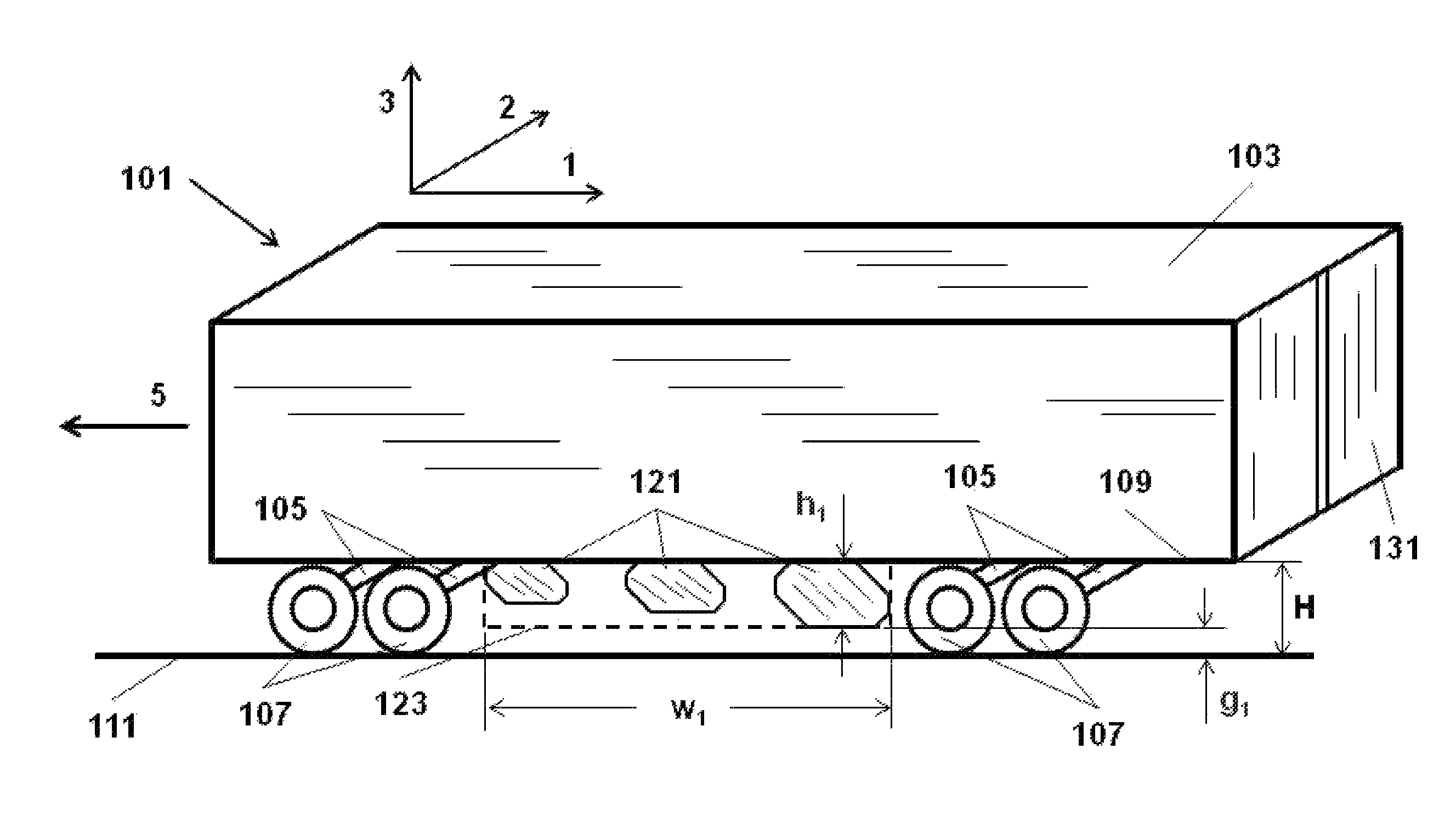
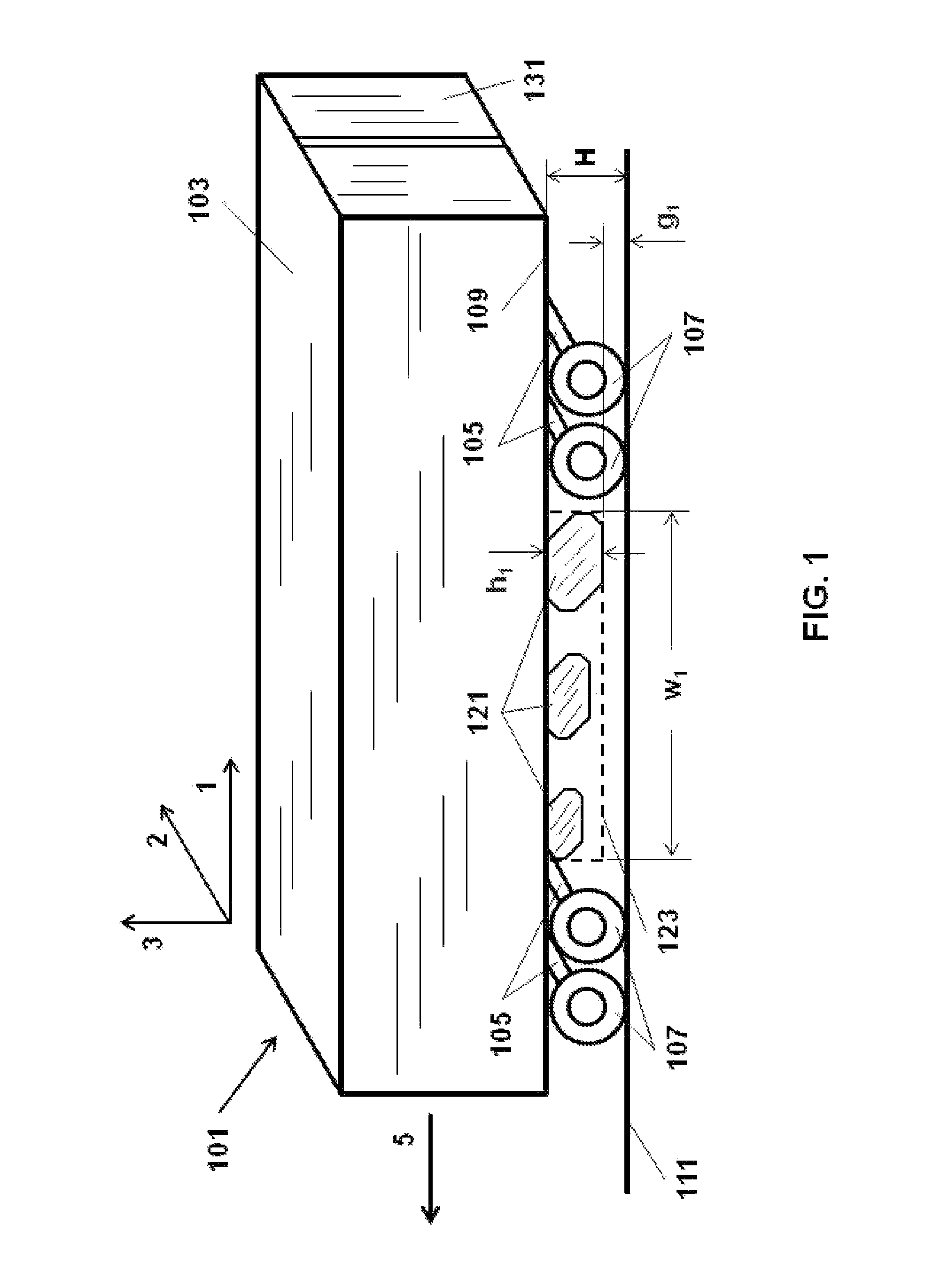
[0031]FIG. 1 shows a general view of one configuration for an aerodynamic skirt, also referred to as a device, according to the present invention on a typical land vehicle and illustrates schematically a meaning of some terms used in the present disclosure. Certain terminology is used for clarity of explanation only and is not to be taken as a limitation of the present invention. A land vehicle is illustrated in FIG. 1 and the following FIGS. 3-5 ...


PUM


Abstract

The invention provides an aerodynamic system and a method for controlling airflow over a land vehicle by self-adaptive aerodynamic means alternatively to essentially impenetrable obstructions. The system comprises at least one aerodynamic skirt disposed under the vehicle body. Each aerodynamic skirt is an assembly of airflow-controlling elements forming a surface of the skirt. The elements obstruct only a part of the surface area and create openings over the remaining part of the area. The airflow-controlling elements are configured to reduce the vehicle air drag and mitigate detrimental impacts of side winds on the vehicle by generating optimum air streams over the openings and away from the openings, creating backward air streams under the body and generating aerodynamic vortex shields.

Description


Claims


Application Information

Patent Timeline
Owner PRASKOVSKAYA ELEANOR
Why Eureka
Try Eureka