
Vehicle Underbody Fairing

a technology for underbody fairings and vehicles, applied in vehicle arrangements, roofs, transportation and packaging, etc., can solve the problems of increased fuel costs, inadequate ground clearance, and substantial damage to the skirt, and achieve the effect of reducing aerodynamic drag

Inactive Publication Date: 2009-06-11
LAWRENCE LIVERMORE NAT SECURITY LLC
View PDF13 Cites 70 Cited by
  • Summary
  • Abstract
  • Description
  • Claims
  • Application Information

AI Technical Summary

Benefits of technology

[0007]One aspect of the present invention includes a vehicle underbody fairing apparatus for reducing aerodynamic drag caused by a vehicle wheel assembly supporting a vehicle body from thereunder, comprising: a fairing body having a fairing front end, a fairing rear end, and a tapered aerodynamic surface comprising a bottom section flanked by left and right side sections which together extend from the fairing front end to the fairing rear end with a substantially U-shaped cross-section that tapers in both height and width; and mounting means for securing the fairing body to an underside surface of the vehicle body, so that the fairing front end is adjacent to and downstream of the vehicle wheel assembly and the bottom section of the tapered aerodynamic surface rises towards the underside surface of the vehicle body as it extends downstream from the fairing front end to the fairing rear end, whereby the mounted fairing body reduces the size of a recirculation zone formed under the vehicle body immediately downstream of the vehicle wheel assembly.
[0008]Another aspect of the present invention includes a vehicle underbody fairing apparatus for reducing aerodynamic drag caused by a vehicle wheel assembly supporting a vehicle body from thereunder, comprising: a fairing body having a fairing front end, a fairing rear end, and a tapered aerodynamic surface comprising a bottom section flanked by left and right side sections which together extend from the fairing front end to the fairing rear end with a substantially U-shaped cross-section that tapers in both height and width from a fairing front end height and width that are substantially equivalent to the height and width respectively of the vehicle wheel assembly to a vertex at the fairing rear end; and mounting means for securing the fairing body to an underside surface of the vehicle body, so that the fairing front end is adjacent to and downstream of the vehicle wheel assembly, the bottom section of the tapered aerodynamic surface rises towards the underside surface of the vehicle body as it extends downstream from the fairing front end to the fairing rear end, and the vertex is at substantially the same level as the underside surface of the vehicle body, whereby the mounted fairing body reduces the size of a recirculation zone formed under the vehicle body immediately downstream of the vehicle wheel assembly.
[0009]And another aspect of the present invention includes an aerodynamic semi-trailer for use in tractor-trailer towing arrangements, comprising: a trailer body with a trailer front end and a trailer rear end; a rear wheel assembly supporting the trailer rear end from thereunder; a hitch located under the trailer front end for connecting the trailer body to a tractor so that a drive wheel assembly of the tractor supports the trailer front end from thereunder; and a fairing body located under the trailer body between the front and rear wheel assemblies, said fairing body having a fairing front end adjacent to and downstream of the drive wheel assembly of the tractor when the trailer body is hitched thereto, a fairing rear end downstream of the fairing front end, and a tapered aerodynamic surface comprising a bottom section flanked by left and right side sections which together extend downstream from the fairing front end to the fairing rear end with a substantially U-shaped cross-section that tapers in both height and width, said bottom section rising towards the underside surface of the vehicle body as it extends downstream from the fairing front end to the fairing rear end, whereby the mounted fairing body reduces the aerodynamic drag caused by the vehicle wheel assembly by reducing the size of a recirculation zone formed under the vehicle body immediately downstream of the vehicle wheel assembly.
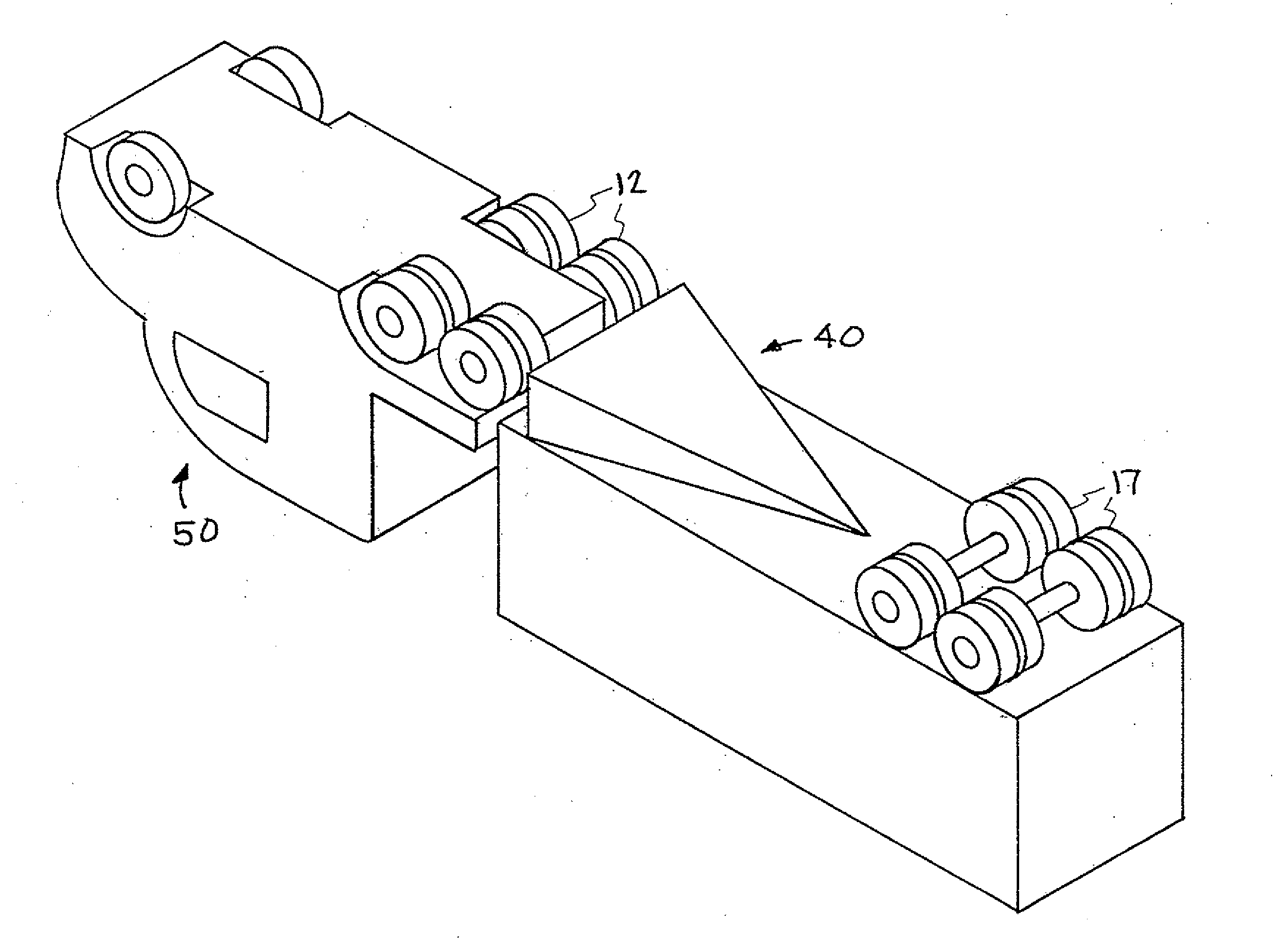
[0011]The underbody fairing apparatus includes two main components: (1) a fairing body having a wide, broad-faced fairing front end, a substantially narrower fairing rear end, and a tapered aerodynamic surface having a bottom section flanked by left and right side sections which together extend from the fairing front end to the fairing rear end with a substantially U-shaped cross-section that tapers in both height and width; and (2) mounting hardware for securing the fairing body to an underside surface of the trailer body so that the front end of the fairing body is adjacent to and downstream of (immediately downstream of) the tractor's drive wheel assembly and a bottom section of the tapered aerodynamic surface rises towards the underside surface of the vehicle body as it extends downstream from the fairing front end to the fairing rear end. When placed in a flowstream in this manner, the underbody fairing apparatus is designed to reduce the size of the recirculation zone on the rear or base of the drive wheel assembly which consequently reduces the overall aerodynamic drag of the vehicle. It is appreciated that the term “fairing” is used herein as a member, structure, or external surface of a vehicle whose primary function is to produce a smooth outline and to reduce drag. And it is appreciated that the mounting hardware can include common fasteners (bolts, nuts, etc), latches, hooks, ties, adhesives, magnets, etc. or other securing methods used for temporary or permanent attachment.

Problems solved by technology

As the aerodynamic drag experienced by a vehicle increases, the fuel costs also correspondingly increase due to the greater energy required to overcome the drag.
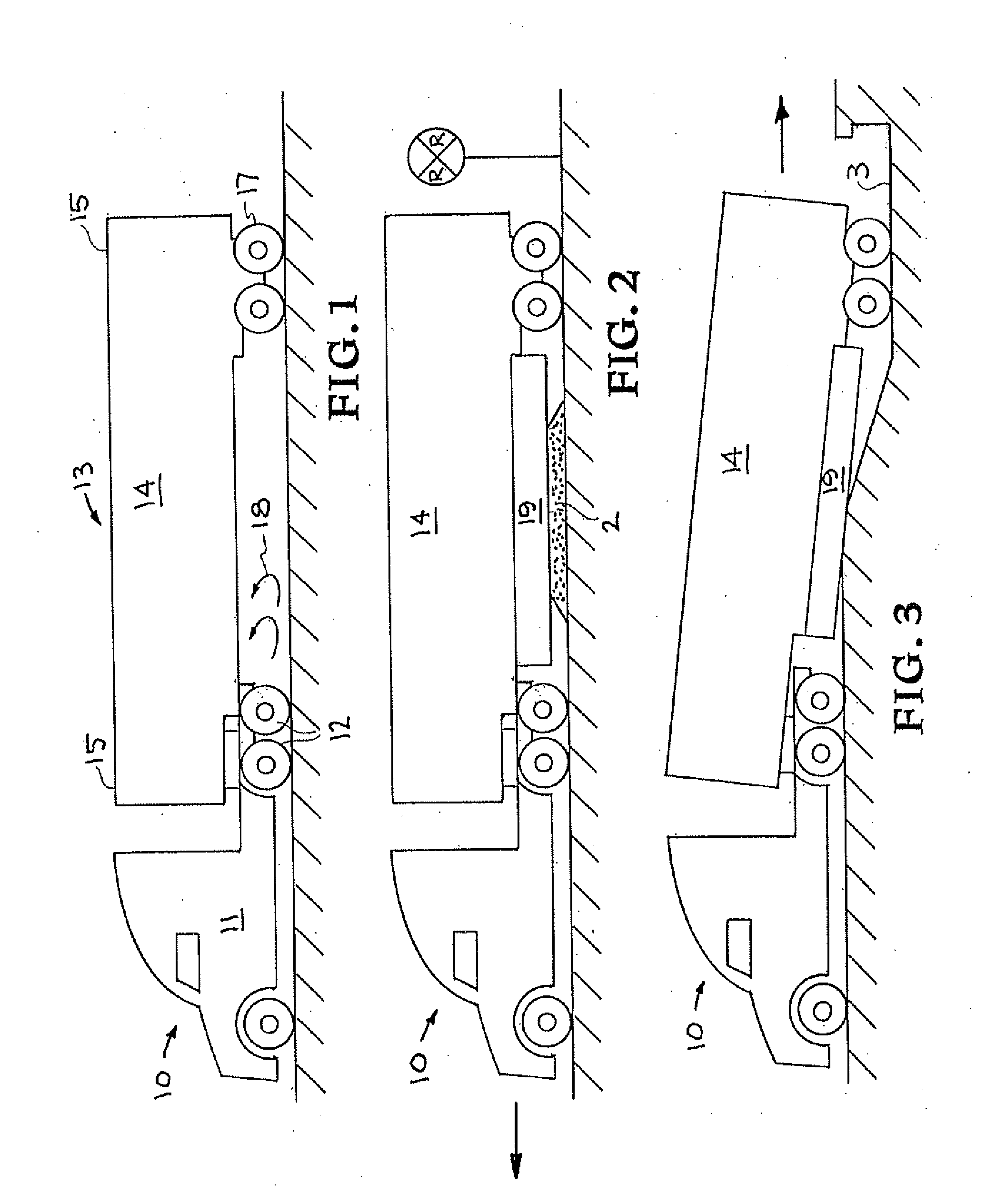
However, as also shown in FIGS. 2 and 3, a potential problem with such underbody skirts is inadequate ground clearance when the semi travels over a raised, protruding, undulating, or otherwise uneven part of the travel surface.
In either case, substantial damage may result to the skirt due to inadequate ground clearance.

Method used


Image

  • Vehicle Underbody Fairing
  • Vehicle Underbody Fairing
  • Vehicle Underbody Fairing

Examples


Embodiment Construction

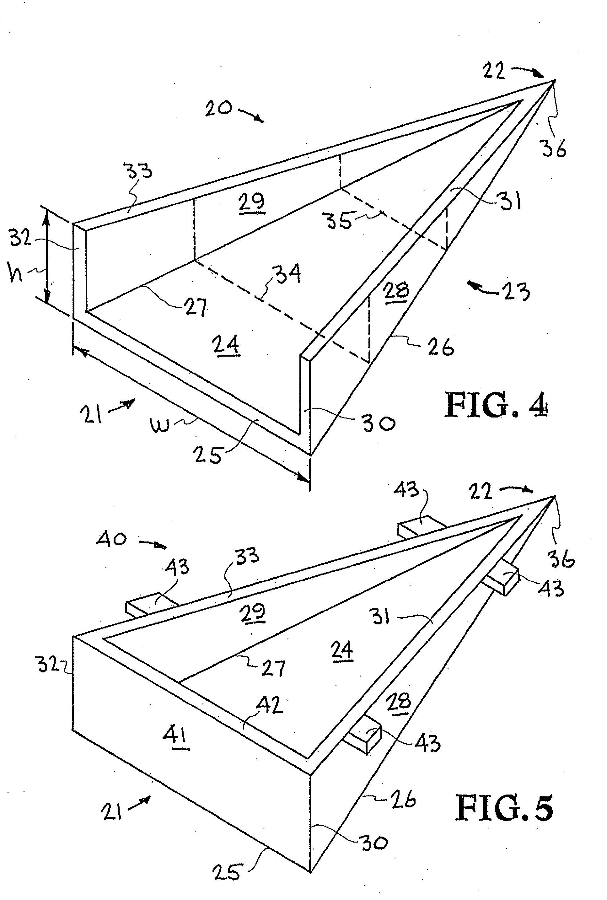
[0028]Turning now to the drawings, FIG. 4 shows a first example embodiment of the vehicle underbody fairing apparatus of the present invention. In particular, FIG. 4 illustrates only the fairing body 20 of the underbody fairing apparatus, with the mounting device / method used for securing the fairing body to a vehicle body not shown. The fairing body 20 may be generally characterized as being wedge shaped, and has a fairing front end 21, a fairing rear end 22, and a tapered aerodynamic surface 23 comprising a bottom section 24 flanked by left 28 and right 29 side sections which together extend from the fairing front end 21 to the fairing rear end 22. The left and right side sections 28, 29 are shown in an upright position with upper edges 31 and 33, respectively, front edges 30 and 32, respectively, and connected along their respective lower edges to the left and right edges, respectively, of the bottom section 24. The lower edge of the left side section 28 and the left edge of the b...


PUM


Abstract

A vehicle underbody fairing apparatus for reducing aerodynamic drag caused by a vehicle wheel assembly, by reducing the size of a recirculation zone formed under the vehicle body immediately downstream of the vehicle wheel assembly. The fairing body has a tapered aerodynamic surface that extends from a front end to a rear end of the fairing body with a substantially U-shaped cross-section that tapers in both height and width. Fasteners or other mounting devices secure the fairing body to an underside surface of the vehicle body, so that the front end is immediately downstream of the vehicle wheel assembly and a bottom section of the tapered aerodynamic surface rises towards the underside surface as it extends in a downstream direction.

Description

CLAIM OF PRIORITY IN PROVISIONAL APPLICATION[0001]This application claims priority in provisional application filed on Oct. 23, 2007, entitled “Drag Reduction of a Heavy Vehicle by Means of a Trailer Underbody Fairing” Ser. No. 60 / 982,002, by Jason M. Ortega et al, and incorporated by reference herein.FEDERALLY SPONSORED RESEARCH OR DEVELOPMENT[0002]The United States Government has rights in this invention pursuant to Contract No. DE-AC52-07NA27344 between the United States Department of Energy and Lawrence Livermore National Security, LLC for the operation of Lawrence Livermore National Laboratory.FIELD OF THE INVENTION[0003]The present invention relates to aerodynamic drag reduction methods. The invention relates more particularly to an underbody fairing apparatus for reducing the underbody drag of a heavy vehicle produced by a wheel assembly supporting the vehicle.BACKGROUND OF THE INVENTION[0004]It is well known in the art of vehicle design that the fuel consumption of a vehicle...

Claims


Application Information

Patent Timeline
IPC IPC(8): B62D35/02
CPCB62D35/02B62D35/001Y02T10/88Y02T10/82
Inventor ORTEGA, JASON M.SALARI, KAMBIZMCCALLEN, ROSE
Owner LAWRENCE LIVERMORE NAT SECURITY LLC
Learn More