
Fairway wood center of gravity projection

Active Publication Date: 2014-12-02
TAYLOR MADE GOLF
View PDF483 Cites 195 Cited by
  • Summary
  • Abstract
  • Description
  • Claims
  • Application Information

AI Technical Summary

Benefits of technology

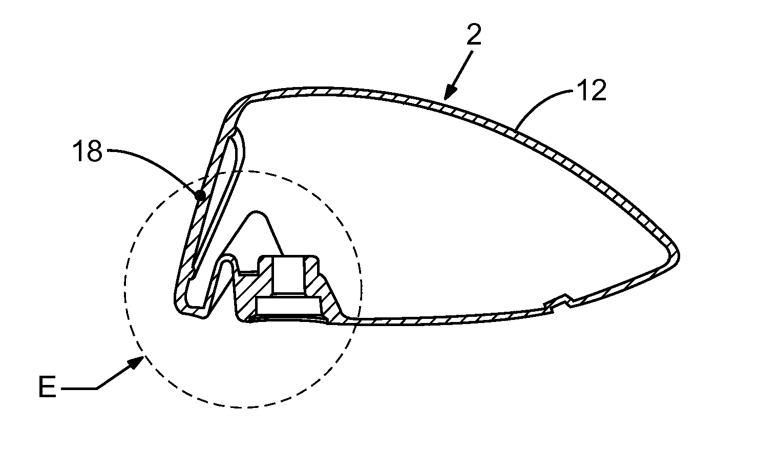
This patent describes golf club heads that have improved forgiveness, ballspeed, and playability while still being durable. In some cases, the club heads have a channel, slot, or other feature that increases the flexibility of the striking face, which leads to increased performance. This feat is located in the forward portion of the club head, near the edge.

Problems solved by technology

Higher golf club head moments of inertia result in lower golf club head rotation on impact with a golf ball, particularly on “off-center” impacts with a golf ball, e.g., mis-hits.
Moreover, higher moments of inertia typically result in greater ball speed on impact with the golf club head, which can translate to increased golf shot distance.
Faced with constraints such as those just described, golf club manufacturers often must choose to improve one performance characteristic at the expense of another.
Thus, conventional golf club heads that offer increased moments of inertia for forgiveness often do not perform well as a fairway wood club head.
Although traditional fairway wood club heads generally have a low CG relative to most traditional drivers, such clubs usually also suffer from correspondingly low mass moments of inertia.
But because of their low mass moments of inertia, traditional fairway wood club heads are less forgiving than club heads with high moments of inertia, which heretofore have been drivers.
As already noted, conventional golf club heads that have increased mass moments of inertia, and thus are more forgiving, have been ill-suited for use as fairway woods because of their relatively high CG.
Accordingly, to date, golf club designers and manufacturers have not offered golf club heads with high moments of inertia for improved forgiveness and low center-of-gravity for playing a ball positioned on turf.
Additionally, due to the nature of fairway wood shots, most such shots are impacted below the center of the face.
For traditionally designed fairway woods, this means that ballspeed and ball launch parameters are less than ideal.
A continual challenge to improving performance in fairway woods and hybrid clubs is the limitation in generating ballspeed.

Method used


Image

  • Fairway wood center of gravity projection
  • Fairway wood center of gravity projection
  • Fairway wood center of gravity projection

Examples


example 1

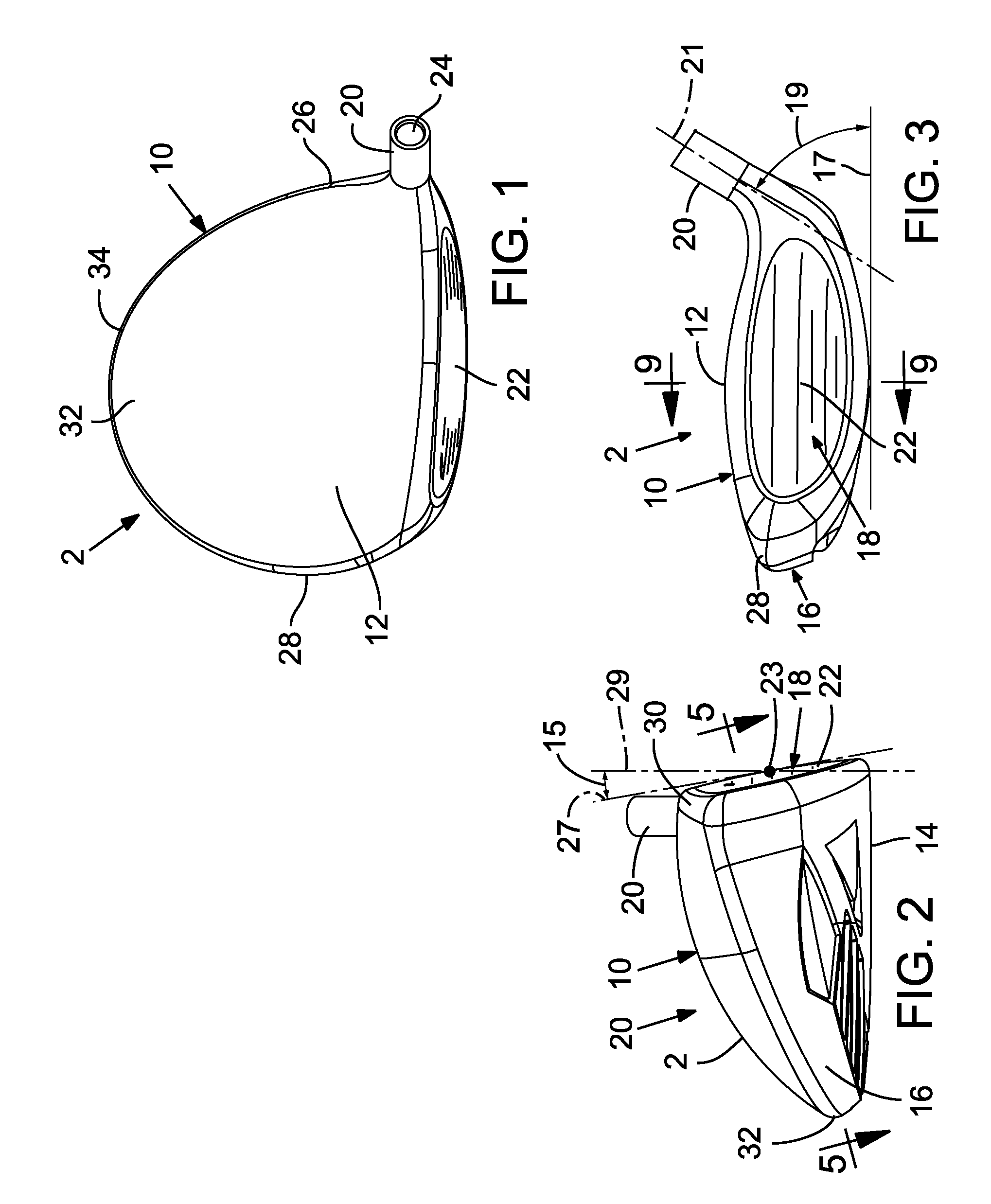
[0184]Club heads formed according to the Example 1 embodiment are formed largely of an alloy of steel. As indicated by Table 1 and depending on the manufacturing tolerances achieved, the mass of club heads according to Example 1 is between about 210 g and about 220 grams and the Zup dimension is between about 13 mm and about 17 mm. As designed, the mass of the Example 1 design is 216.1 g and the Zup dimension 15.2 mm. The loft is about 16 degrees, the overall club head height is about 38 mm, and the head depth is about 87 mm. The crown is about 0.60 mm thick. The relatively large head depth in combination with a thin and light crown provides significant discretionary mass for redistribution to improve forgiveness and overall playability. For example, the resulting mass moment of inertia about the CG z-axis (Izz) is about 325 kg-mm2.

example 2

[0185]Club heads formed according to the Example 2 embodiment are formed largely of an alloy of titanium. As indicated by Table 1 and depending on the manufacturing tolerances achieved, the mass of club heads according to Example 2 is between about 210 g and about 220 grams and the Zup dimension is between about 13 mm and about 17 mm. As designed, the mass of the Example 2 design is 213.8 g and the Zup dimension 14.8 mm. The loft is about 15 degrees, the overall club head height is about 40.9 mm, and the head depth is about 97.4 mm. The crown is about 0.80 mm thick. The relatively large head depth in combination with a thin and light crown provides significant discretionary mass for redistribution to improve forgiveness and overall playability. For example, the resulting mass moment of inertia about the CG z-axis (Izz) is about 302 kg-mm2.

examples 1 and 2

Overview of Examples 1 and 2

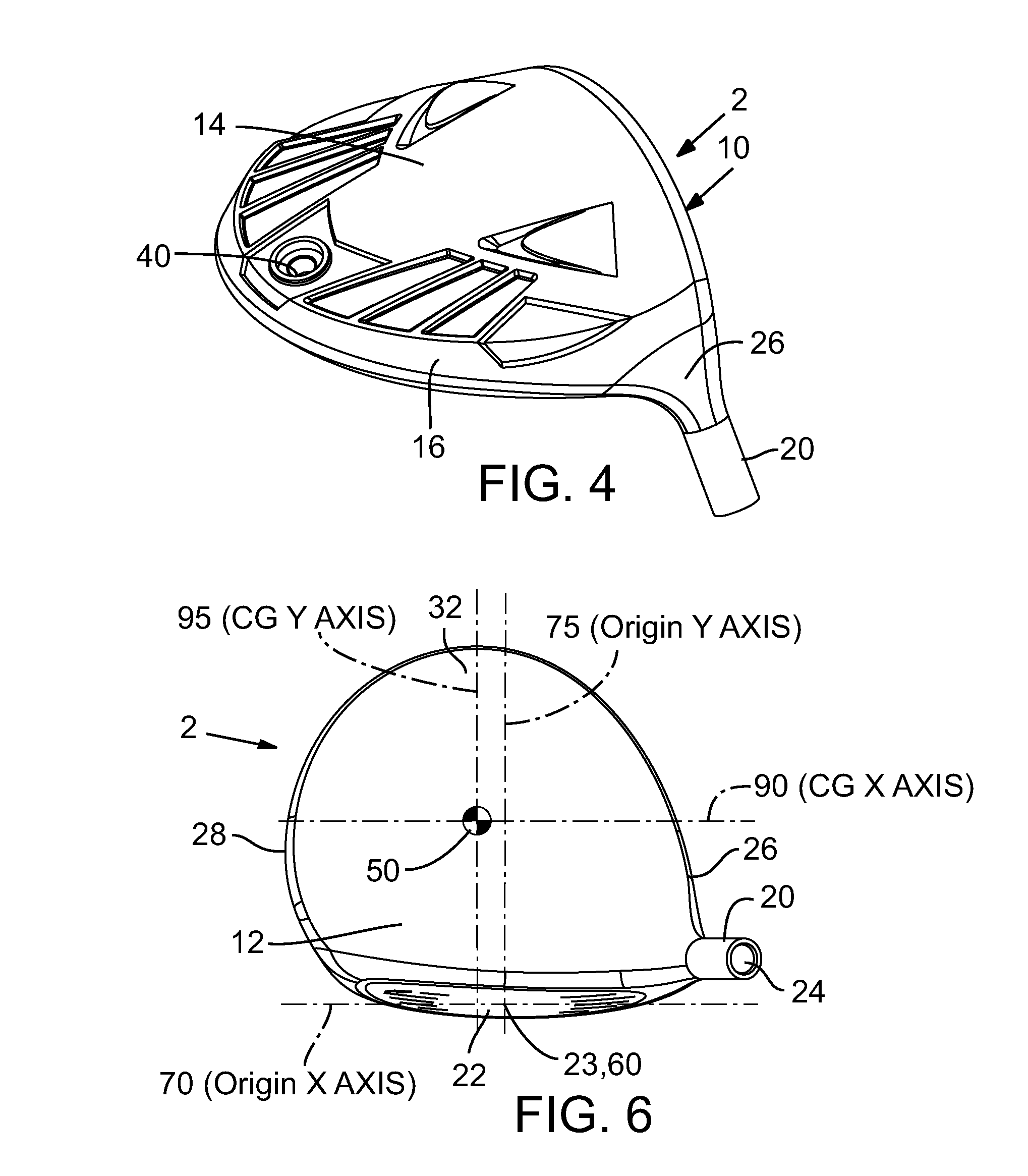
[0186]Both of these examples provide improved playability compared to conventional fairway woods, in part by providing desirable combinations of low CG position, e.g., a Zup dimension less than about 16 mm, and high moments of inertia, e.g., Izz greater than about 300 kg-mm2, Ixx greater than about 170 kg-mm2, and a shallow head height, e.g., less than about 46 mm. Such examples are possible, in part, because they incorporate an increased head depth, e.g., greater than about 85 mm, in combination with a thinner, lighter crown compared to conventional fairway woods. These features provide significant discretionary mass for achieving desirable characteristics, such as, for example, high moments of inertia and low CG.

[0187]

TABLE 1ExemplaryEmbodimentUnitsExample 1Example 2Massg216.1213.8Volumecc181.0204.0CGXmm2.54.7CGYmm31.836.1CGZmm−3.54−4.72Z Upmm15.214.8Loft°1615Lie°58.558.5Face Heightmm26.330.6Head Heightmm3840.9Face Thicknessmm2.002.30Crown Thicknessmm0....


PUM


Abstract

A golf club head includes a body defining an interior cavity. The body includes a sole positioned at a bottom portion of the golf club head, a crown positioned at a top portion, and a skirt positioned around a periphery between the sole and crown. The body has a forward portion and a rearward portion. The club head includes a face positioned at the forward portion of the body. The face defines a striking surface having an ideal impact location at a golf club head origin. Embodiments include club heads for a fairway wood that at least one of a high moment of inertia, a low center-of-gravity, a thin crown and a high coefficient of restitution.

Description

CROSS REFERENCE TO RELATED APPLICATIONS[0001]This application claims the benefit of U.S. Provisional Patent Application No. 61 / 427,772, filed Dec. 28, 2010, which is incorporated herein by reference.FIELD[0002]The present application concerns golf club heads, and more particularly, golf club heads having unique relationships between the club head's mass moments of inertia and center-of-gravity position, golf club heads having a center of gravity projection that is near the center of the face of the golf club, golf club heads having unique relationships between loft and center of gravity projection location, and golf club heads having increased striking face flexibility.INCORPORATIONS BY REFERENCE[0003]Other patents and patent applications concerning golf clubs, such as U.S. Pat. Nos. 7,407,447, 7,419,441, 7,513,296, and 7,753,806; U.S. Pat. Appl. Pub. Nos. 2004 / 0235584, 2005 / 0239575, 2010 / 0197424, and 2011 / 0312347; U.S. patent application Ser. Nos. 11 / 642,310, and 11 / 648,013; and U....

Claims


Application Information

Patent Timeline
IPC IPC(8): A63B53/06A63B53/04A63B53/02
CPCA63B53/0466A63B2053/0433A63B2053/0412A63B2053/0408A63B53/02A63B53/06A63B2053/0491A63B53/0487A63B53/047A63B2209/00A63B2053/023A63B2053/045A63B2209/02A63B60/52A63B53/0412A63B53/0408A63B53/045A63B53/0433A63B53/023
Inventor BEACH, TODD P.JOHNSON, MATTHEW DAVIDSARGENT, NATHAN T.WILLETT, KRAIG ALANPENNEY, MICHELLEKRONENBERG, MARCGREENSMITH, MATTHEWHOFFMAN, JOSEPH HENRY
Owner TAYLOR MADE GOLF
Learn More