

Golf club head with progressive face stiffness
a golf club head and face stiffness technology, applied in the field of multi-material, multi-component metal wood golf club heads, can solve the problems of increasing the weight of the club head, increasing the thickness of the shell, and enlarging the club head, so as to reduce the coefficient of restitution, increase the face stiffness, and lower the spinning trajectory
- Summary
- Abstract
- Description
- Claims
- Application Information
AI Technical Summary
Benefits of technology
Problems solved by technology
Method used
Image

Examples
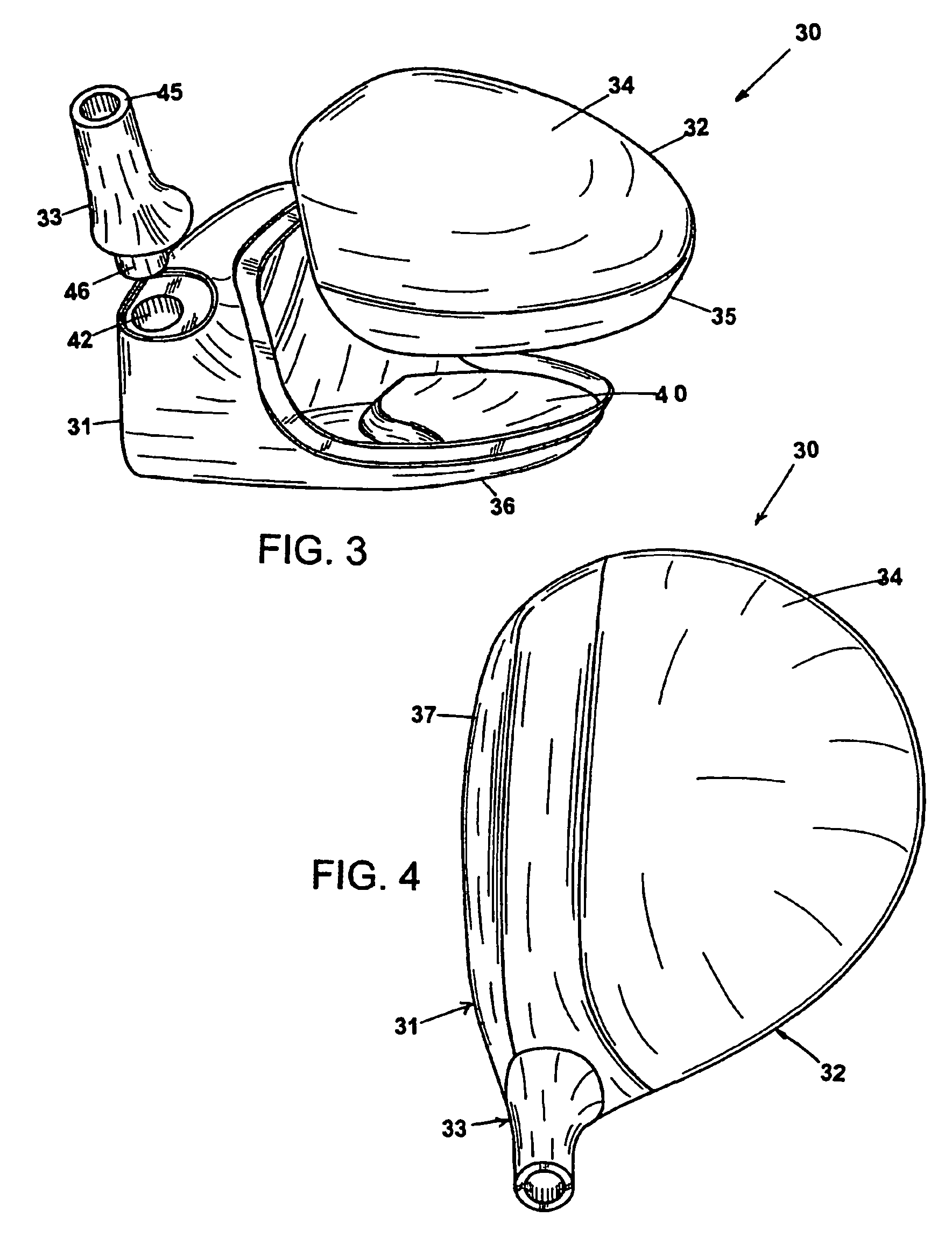
embodiment 30
[0075]An alternate embodiment, depicted by FIGS. 9-12, and referred to as club head 50, illustrates the advantage of injection molding the second body portion, wherein a hosel section 51 and bore-thru-hosel tube 52 are integrated with a crown section 53 to form a crown portion 54. The advantage is that even more of the “high section” of the club head is made from a low density material (compared to the club head of embodiment 30 where bore-thru is made of higher density material). This allows for further lowering of the center of gravity C. The challenge is that the hosel is typically less rigid when made of low density material. Conventional golf clubs typically include a hosel welded on to the body of the club, which requires more manufacturing time and increases the complexity of manufacturing.
[0076]Alternatively, the club head of the present invention may also be used with the smaller fairway woods, which can have volume as low as about 150 cubic centimeters. Preferably, the mas...
first embodiment
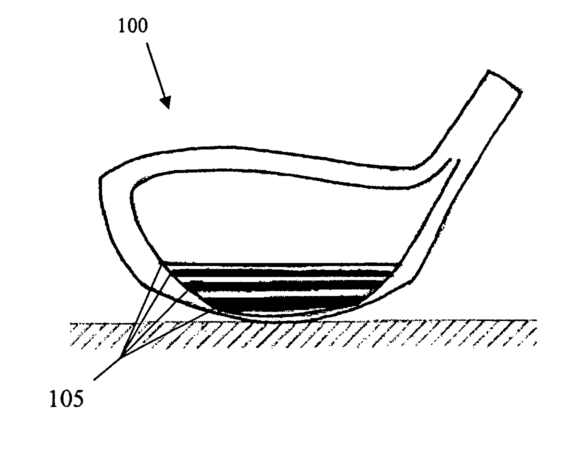
[0079]FIG. 22 shows a face view of a club head 100 with a stiffening insert 105, and FIG. 23 shows a toe-side view of this embodiment. The club head 100 includes a face, a crown, a sole, and a skirt coupled together to form a club head body having an interior volume. In this embodiment, the insert 105 is provided in the form of ribs. The ribs are attached to the inner surface of the face, within the interior volume. The ribs are spaced apart, preferably at regular intervals, and are oriented vertically in a sole-to-crown direction. While five ribs are shown in the illustrated embodiment, any number of ribs may be used. Three to seven ribs are preferred. Each of the ribs is wider at the sole end than at the crown end, thereby imparting more stiffness to the sole end of the face than the crown end. It should be noted that the ribs can extend from the sole all the way to the crown, or they may extend only partially up the face and not reach the crown. The ribs are wider at a sole end t...
PUM
 Abstract
Description
Claims
Application Information