
Wheel and wheel assembly

a technology of wheel and assembly, which is applied in the direction of climbing vehicles, vehicle components, transportation and packaging, etc., can solve the problems of increasing energy expenditure, inconvenient or impossible to move the mobile platform in the field, and increasing so as to reduce the sinkage of the wheel or the mobile platform. , the effect of expanding the footprint of the mobile platform

Active Publication Date: 2014-12-09
ROSS ROBOTICS
View PDF25 Cites 10 Cited by
  • Summary
  • Abstract
  • Description
  • Claims
  • Application Information

AI Technical Summary

Benefits of technology

The wheel described in this patent is designed to move loads over rough terrain, such as stairs or hard floors, and has a unique shape that allows for efficient movement. However, when moving over smooth surfaces, the wheel may cause more energy expenditure due to its unique shape and design. In response, the patent describes a wheel assembly that includes two wheels with complementary shapes that save space and decrease sinking or snagging. The technical effects are improved efficiency and a compact, stable wheel assembly for various terrains.

Problems solved by technology

This leads to inefficient movement of the mobile platform because the wheels are adapted for movement across smooth surfaces and are badly adapted to traversing irregular or absorbent terrain types, e.g. a car with smooth road tyres is inefficient when traversing wet muddy fields, a trolley is difficult to push over gravel car parks.
Although the tyres or even the entire wheel may be changed in advance to suit different terrain types, it is usually inconvenient or impossible to do so in the field and without specialist machinery.
This leads to an increase in energy expenditure when traversing smooth ground because the cycloidal motion requires the mass of the load to be repeatedly raised and lowered.
In addition, the profile of this wheel, in particular the extremity points at which the involute curves intersect, may cause the wheel to snag in hard and / or irregular surfaces or to snag on debris such as branches or bushes, and on soft and / or absorbent surfaces the wheel will tend to sink.
These issues will result in even more energy expenditure to move a load over variable terrain.
Although the thin arcuate spines are suitable for this type of robot due to its portability and lightweight nature, the spines may not be suitable for use on larger heavier mobile platforms or robots or for carrying heavier payloads over variable terrain.
In addition, the thin spines will become snagged on debris or irregularities in rough terrain such as small cracks and crevices decreasing the efficiency of the robot or toy and even immobilising it.

Method used


Image

  • Wheel and wheel assembly
  • Wheel and wheel assembly
  • Wheel and wheel assembly

Examples


example 1

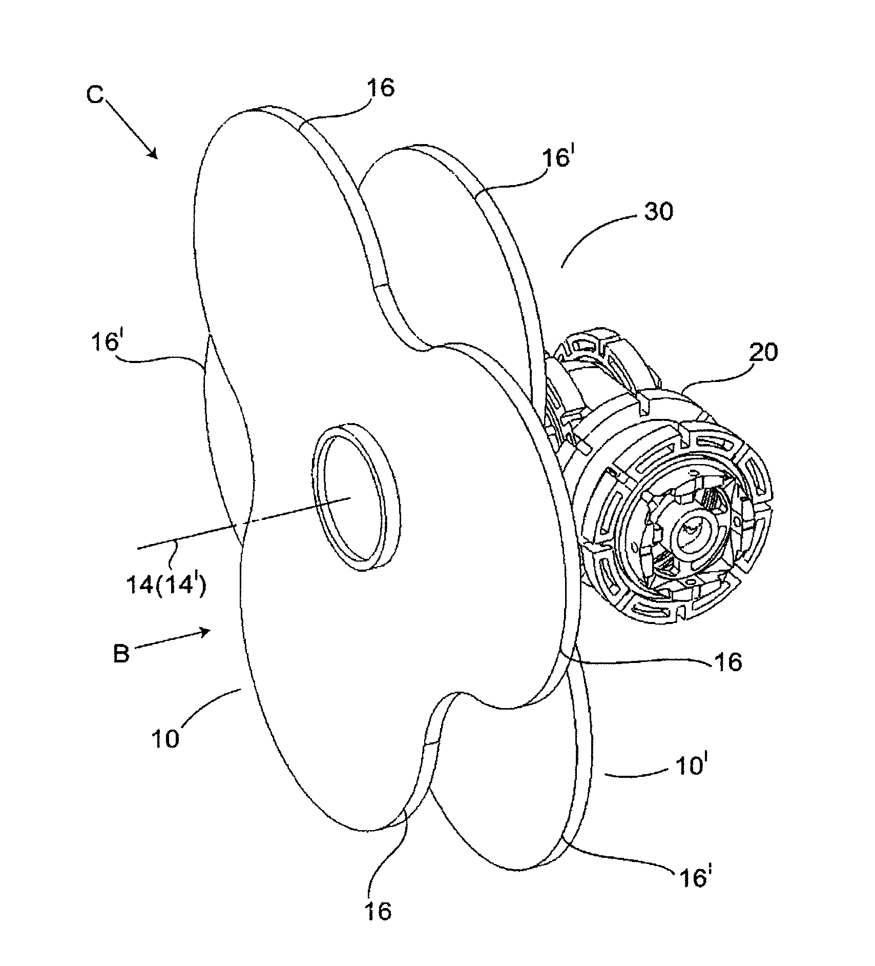
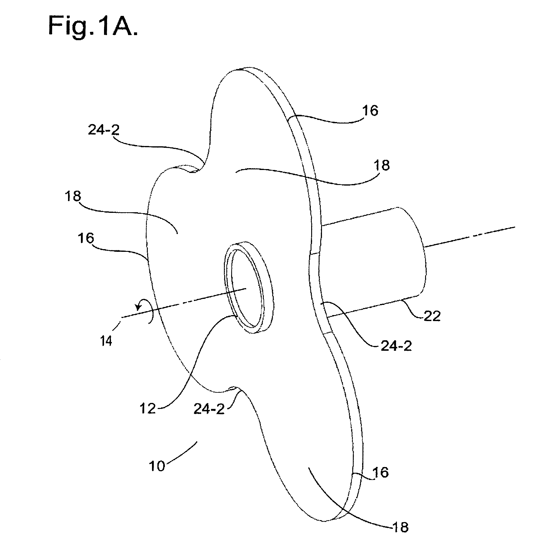
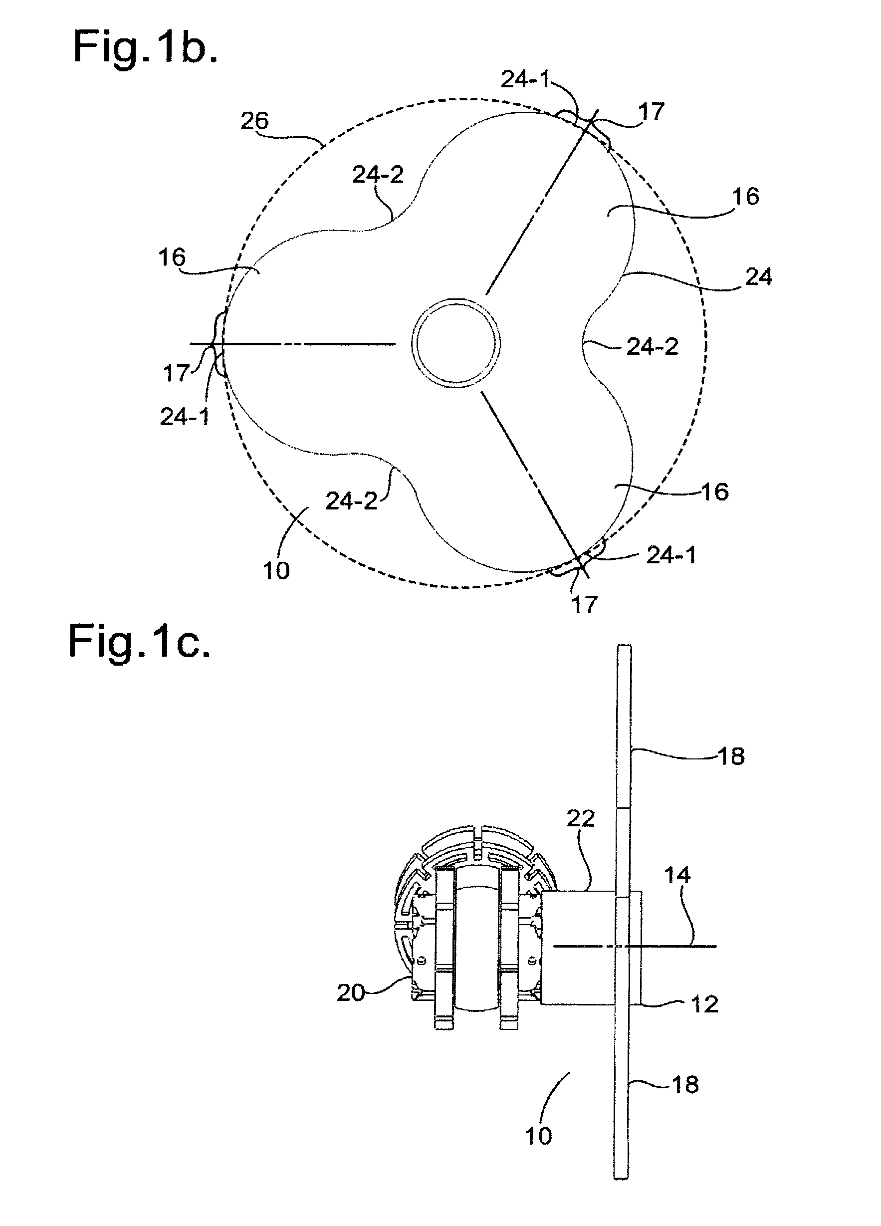
[0199]A wheel assembly for a mobile platform, the wheel assembly including a first wheel and a second wheel, each wheel comprising a hub having a central axis of rotation, and at least two wheel lobes coupled to the hub, the wheel lobes extending radially from the hub and spaced around the central axis of the hub, where the first wheel is rotatably mounted to the second wheel and the central axes of rotation of the first and second wheels are coaxial and so define a common axis. The wheel assembly further includes a control mechanism for adapting the wheel assembly from a first state to a second state by rotating the first wheel with respect to the second wheel around the common axis, where the first state has the first and second wheels positioned such that a wheel lobe of the first wheel is substantially aligned with a corresponding wheel lobe of the second wheel, and the second state has the first and second wheels positioned such that a wheel lobe of the first wheel and a corres...

example 2

[0200]A wheel assembly based on example 1, further including wheel lobes each having a curved edge around a region of the lobe edge furthest away from the hub.

example 3

[0201]A wheel assembly based on examples 1 or 2, where the wheel lobes each define a convex curved surface at one side of the wheel assembly.


PUM


Abstract

A wheel assembly and a wheel are suitable for use with a mobile platform. The wheel assembly comprising a first wheel and a second wheel, each wheel comprising a hub having a central axis of rotation, and at least two wheel lobes coupled to the hub, the wheel lobes extending radially from the hub and spaced around the central axis of the hub, where the first wheel is rotatably mounted to the second wheel on a common axis, and a control mechanism rotates the first wheel with respect to the second wheel.

Description

INTRODUCTION[0001]The present invention relates to a wheel and wheel assembly for a mobile platform such as a robot or vehicle for use over varying terrain types and / or bodies of water.[0002]Wheels are used for many different purposes that require the efficient movement of an object across a surface where there is a force such as gravity pressing the object to the surface. Common examples are found in transport applications such as a cart pulled by a horse, hand trucks or trolleys for shifting loads, other vehicles such as cars and trucks, or the landing gear of an aircraft.[0003]The terms mobile platform or vehicle are used interchangeably to refer to any movable frame or chassis having at least one wheel for moving the frame across, through, or over a surface. Examples of mobile platforms include, but are not limited to, toys, toy robots, wheel barrows, hand trucks, trolleys, trailers, robots, cars, trucks, or amphibious vehicles.[0004]Most wheels are typically circular, cylindric...

Claims


Application Information

Patent Timeline
Patent Type & Authority Patents(United States)
IPC IPC(8): B60B11/02B60B11/00
CPCB60B11/02B60Y2200/48B60B19/00B62B9/06
Inventor NORMAN, PHILIP
Owner ROSS ROBOTICS
Learn More