Feeding-bottle sterilizer

a feeding-bottle and sterilizer technology, applied in the field of feeding-bottle sterilizer, can solve the problems of long sterilization time and incomplete feeding-bottle sterilization, and achieve the effects of shortening the sterilization time, rapid and even steam distribution, and improving sterilization efficiency

Active Publication Date: 2014-12-09
HUIYANG ALLAN PLASTIC & ELECTRIC INDS
View PDF3 Cites 6 Cited by
  • Summary
  • Abstract
  • Description
  • Claims
  • Application Information

AI Technical Summary

Benefits of technology

[0011]The present utility model provides a feeding-bottle sterilizer, wherein the baffle can slow down the overflow of steam outside the sterilizer which can rapidly reach the sterilization temperature and shorten the sterilization time after operation: the air cap of the first steam nozzle can rotate 360 degrees to ensure the rapid and even steam distribution in a space, the second steam nozzle directly stretches into the cavity of the feeding bottle and the third steam nozzle directly extends into the upper basket. Under the coaction of three steam nozzles, it takes little time to fill the entire sterilization space with steam which can distributes evenly, making the feeding-bottle sterilization more rapidly and thoroughly; the feeding-bottle holder is so arranged that the second steam nozzle can stretch into the feeding-bottle cavity without contacting with the inner wall of the feeding bottle, thus reaching a better sterilization effect; the upper cap, baffle, upper basket, feeding-bottle holder, container and base are removable mounding structure, making the entire machine cleaned conveniently and thoroughly.

Problems solved by technology

This feeding-bottle sterilizer addresses technical problems below, such as incomplete feeding-bottle sterilization and long sterilization time.

Method used


Image

  • Feeding-bottle sterilizer
  • Feeding-bottle sterilizer
  • Feeding-bottle sterilizer

Examples


Embodiment Construction

[0016]The present invention is detailed in combination with the drawings below to facilitate the better understanding of the technical solution of the present invention for technicians skilled in this art.

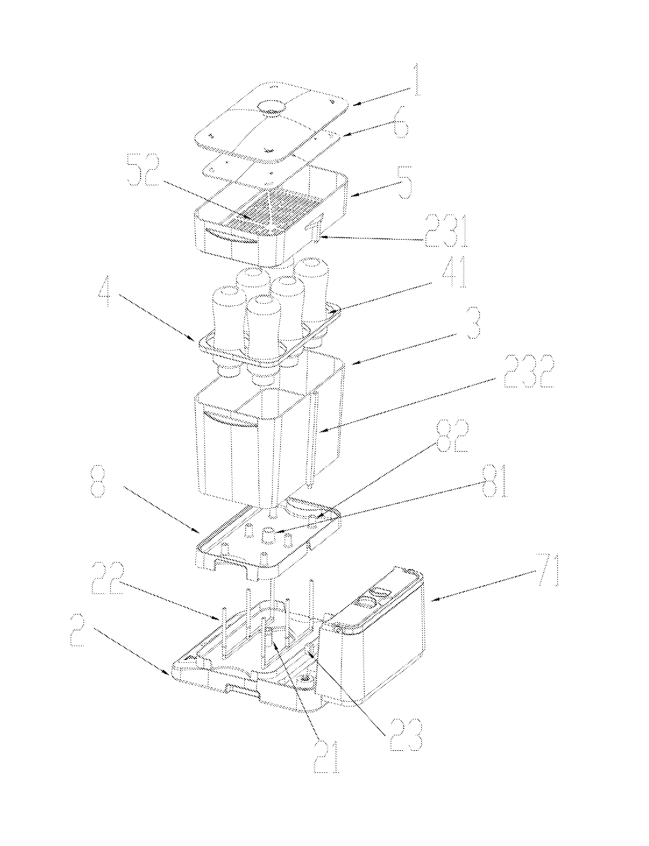
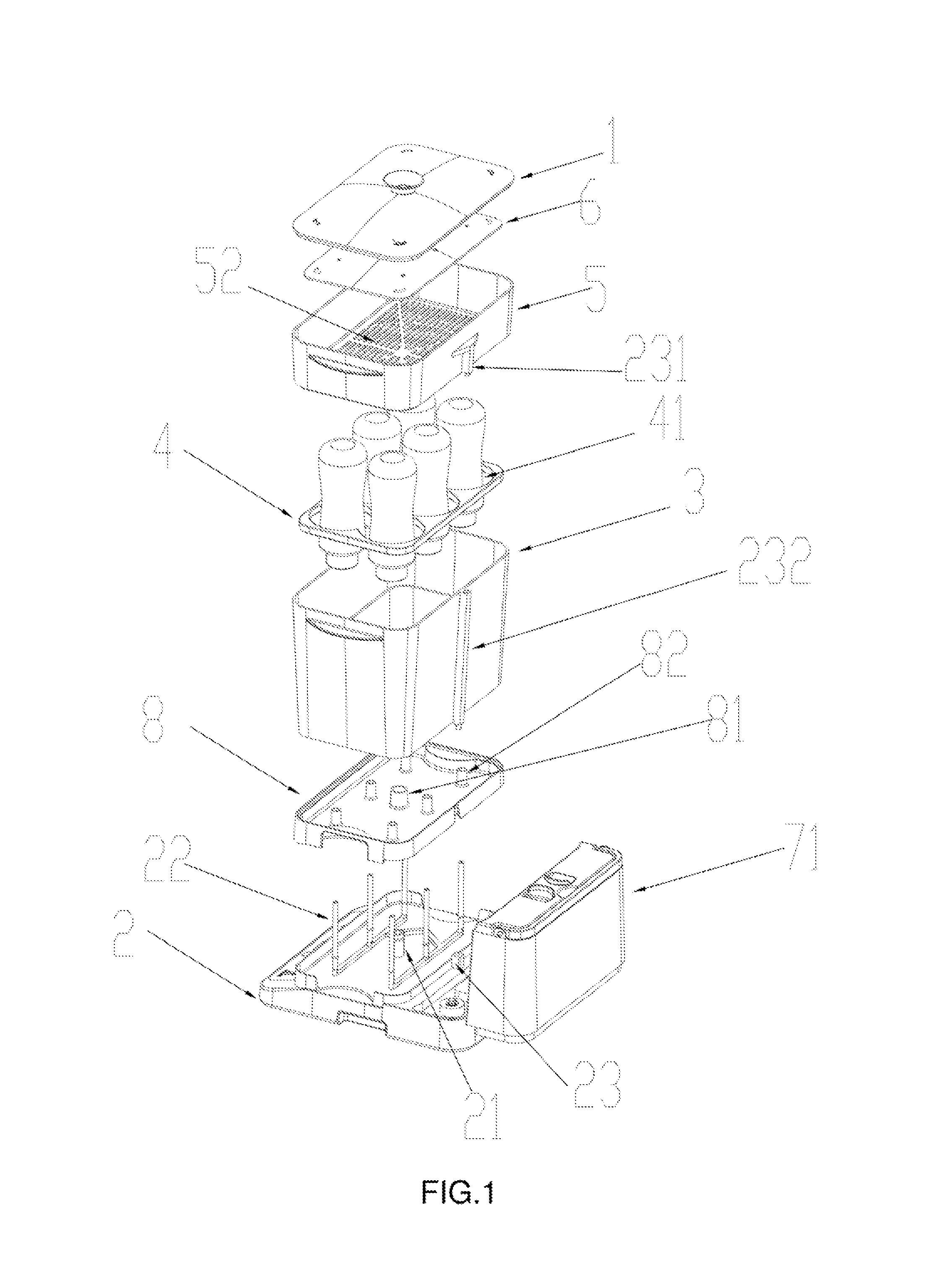
[0017]As shown in FIGS. 1˜4, the present invention discloses a feeding-bottle sterilizer, comprising an upper cap 1, a base 2 and a container 3 between the upper cap 1 and the base 2 for holding one or more feeding bottles to be sterilized, a removable feeding-bottle holder 4 is placed in the container 3, wherein one or more placing holes 41 for placing the one or more feeding bottles upside down are arranged on the feeding-bottle holder. An upper basket 5 is arranged between the container 3 and the upper cap 1 and is used mainly for holding a nipple, a placing mesh 52 allowing the steam passing through is arranged at the bottom of the upper basket and is used for placing a nipple, an air jet hole 231 is connected with the third steam nozzle 23 in series and arranged on the externa...


PUM

PropertyMeasurementUnit
temperatureaaaaaaaaaa
boilingaaaaaaaaaa
timeaaaaaaaaaa

Abstract

The present invention discloses a feeding-bottle sterilizer, comprising an upper cap, a base, and a container in which a feeding-bottle holder is placed, wherein an upper basket is arranged between the container and the upper cap, a baffle is arranged between the upper cap and the upper basket, a barrier is arranged between the base and the container, the baffle can slow down the steam flow out of the sterilizer, and a first, second, and third steam nozzle and a steam supply device are arranged on the base. The air cap of the first steam nozzle can rotate 360 degrees to ensure rapid and even steam distribution in space, the second steam nozzle stretches into the feeding bottle for sterilizing the feeding-bottle cavity, and the third steam nozzle extends into the upper basket. Furthermore, the feeding-bottle sterilizer has advantages of convenient cleaning, quick, and thorough sterilization.

Description

BACKGROUND OF THE INVENTION[0001]The present invention relates to a sterilizer for a feeding-bottle, and more especially, to a feeding-bottle sterilize adopting the high-temperature steam sterilization.[0002]People sterilize feeding bottles and nipples with boiling hot water generally, but this sterilization method is very complicated as it requires taking some time to boil water. Therefore, it takes a long time to complete the sterilization process. A feeding-bottle sterilizer currently appearing on the market heats and evaporates water into water vapor by a heating device and performs sterilization by the high-temperature water vapor in many forms. One is a container with simple structure, comprising a heating device and upper cap, but this kind of feeding-bottle sterilizer forms a larger sterilization space and it takes a longer time to fill the entire sterilization space with steam, thus causing the problem of non-thorough sterilization due to short sterilization time. Another i...

Claims


Application Information

Patent Timeline
Patent Type & Authority Patents(United States)
IPC IPC(8): A61L2/07A61L2/20
CPCB05B3/02B05B3/06A61L2202/23A61L2202/15A61L2/20A61L2/07B08B9/34A47L15/0065B05B3/001
Inventor CHEUNG, SHU SANGPANG, TO YIN
Owner HUIYANG ALLAN PLASTIC & ELECTRIC INDS
Why Eureka
Try Eureka