Reinforced laminated support mat

a technology of support mats and reinforcements, applied in single-unit pavings, bridges, roads, etc., can solve the problems of deflecting or bending of support mats, steel reinforcements not fully recovering to their original shape, and wood panels are typically untreated with preservatives

Active Publication Date: 2014-12-09
ANTHONY HARDWOOD COMPOSITES
View PDF39 Cites 34 Cited by
  • Summary
  • Abstract
  • Description
  • Claims
  • Application Information

AI Technical Summary

Problems solved by technology

The wood panels are typically untreated with preservative chemicals because of environmental concerns.
Support mats are known to deflect or bend when a load is applied to an upper or load-bearing surface of the support mat.
However, upon removal of the load, the steel reinforcement will not fully recover to its original shape and the support mat will experience a permanent deflection.

Method used


Image

  • Reinforced laminated support mat
  • Reinforced laminated support mat
  • Reinforced laminated support mat

Examples


first embodiment

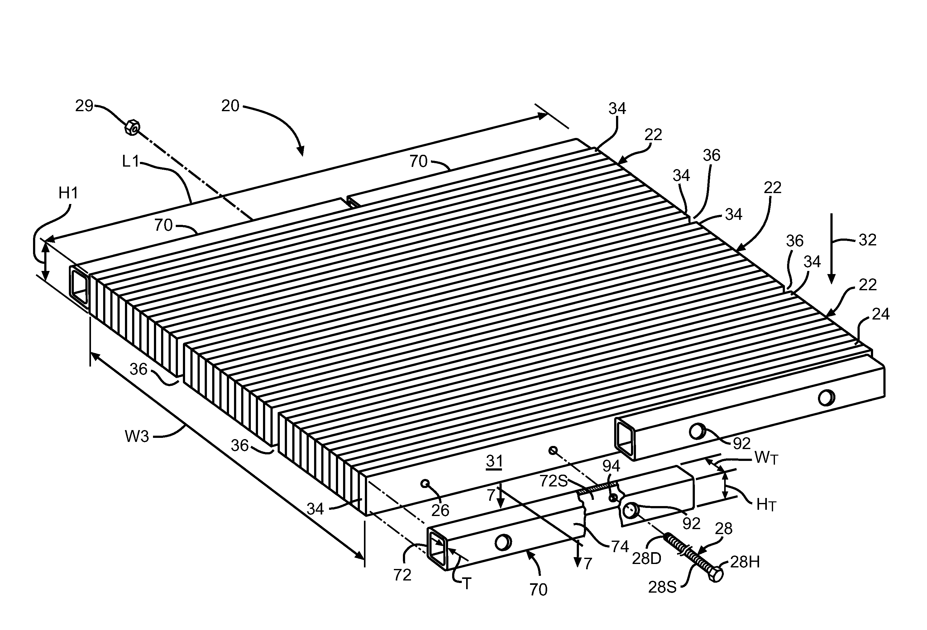
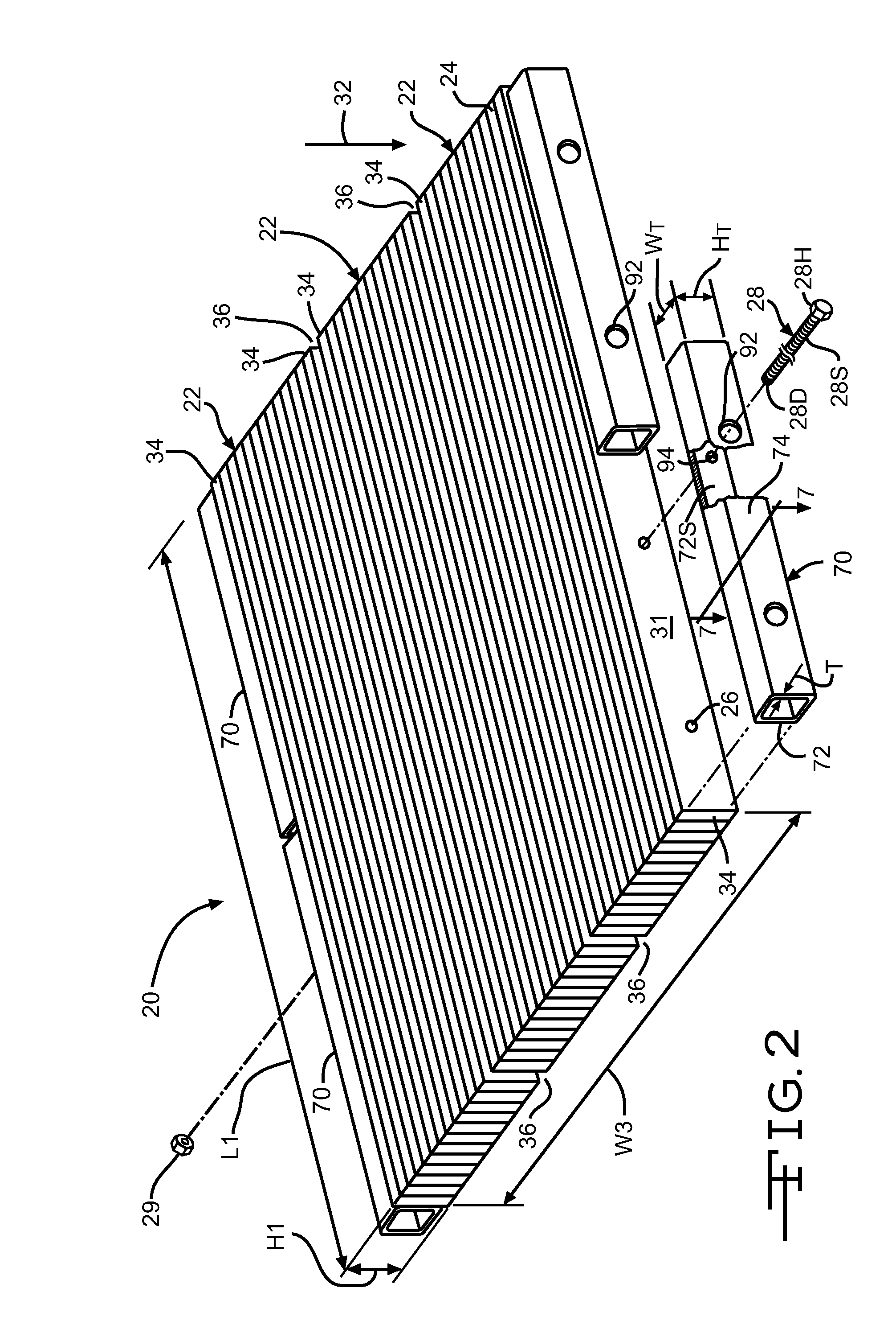
[0025]Referring now to FIG. 2, a laminated support mat is indicated generally at 20. The illustrated laminated support mat 20 is comprised of a plurality of laminated beams or billets 22 and has a substantially planar wide or load-bearing face 96.

[0026]Each of the illustrated billets 22 comprises a plurality of wood members or individual wood laminations 24. Apertures 26 may be formed through the laminated support mat 20 for receiving fastening means, such as the substantially rigid fasteners or bolts 28, as will be described in detail herein. As used in the description of the invention, the term “mat” includes mats as well as panels. Examples of such a support mat are described in co-assigned U.S. Pat. Nos. 7,137,226 and 7,818,929, herein incorporated by reference in their entirety.

[0027]The individual wood laminations 24 may be fabricated by structurally joining together arbitrary or different lengths or strips of wood or wood material. The arbitrary strips of wood material may be...

second embodiment

[0042]One example of such an alternative embodiment is illustrated in FIG. 11 wherein a laminated support mat is shown at 98. The laminated support mat 98 has a length L3 of about 14 feet. The laminated support mat 98 includes three protective edge members. The outboard protective edge members (to the left and right when viewing FIG. 11) are the protective edge members 70 described in detail above. The centrally mounted protective edge member 100 is substantially similar to the protective edge members 70, but has a length L4 of slightly less than 6.0 feet, such as about 71.875 inches, and has three pairs of apertures 90. Alternatively, the protective edge members 70 may have a length L4 a within the range of from about 71.5 inches to about 71.875 inches. Additionally, the protective edge members 70 may have a length L4 less than about 71.5 inches.

third embodiment

[0043]Another example of such an alternative embodiment is illustrated in FIG. 12 wherein a laminated support mat is shown at 102. The laminated support mat 102 has a length L5 of about 18 feet. The laminated support mat 102 includes three of the protective edge members 100 described in detail above.

[0044]In the embodiments illustrated in FIGS. 2 and 4, a plurality of laminated billets 22 is attached to one another to form the laminated support mat 20. In the illustrated embodiment, the wide faces 30 of the outboard laminations 34 of adjacent billets 22 are disposed such that a space 36, the purpose of which will be described in detail below, is defined between the adjacent billets 22. The three laminated billets 22 illustrated in FIG. 2 further define a width W3 for the entire laminated support mat 20. It will be understood that the laminated support mat 20 may have any desired width W3. As best shown in FIG. 2, the laminated support mat 20 also has a height H1 and a length L1. It ...


PUM

PropertyMeasurementUnit
lengthaaaaaaaaaa
lengthaaaaaaaaaa
lengthaaaaaaaaaa

Abstract

A support mat includes a plurality of vertically oriented individual wood members adhesively bonded to each other, each of the individual wood members having wide faces oriented parallel to a direction of a load applied to the support mat, the support mat having outboard wood members, the outwardly facing wide faces of the outboard wood members defining a wide face of the support mat. The support mat also includes least two protective edge members, each protective edge member having an inboard wide face, each of the at least two protective edge members positioned against one the wide faces of the support mat. At least two substantially rigid fasteners extend through and connect each of the protective edge members and adjacent wood members. The wood members, protective edge members, and fasteners define a substantially rigid support mat having a substantially planar wide face.

Description

BACKGROUND OF THE INVENTION[0001]Various embodiments of a laminated support mat are described herein. In particular, the embodiments described herein relate to an improved laminated support mat and a method of manufacturing such an improved laminated support mat.[0002]The construction industry utilizes solid sawn wood and wood panel members in a variety of forms to aid in the erection of buildings, roads, and bridges. For example, temporary road panels and crane mats are often constructed using solid-sawn hardwood timbers or some species of softwoods. These panels are used to form a temporary lightweight roadway or foundation to facilitate vehicular and equipment travel as may be required in construction operations. Other industry users of such mats include users in the field of pipeline, utility, transportation, oil, and infrastructure.[0003]As shown in FIG. 1, a conventional road panel, shown generally at 10, is formed by using a plurality of solid sawn timber elements 12. Typical...

Claims


Application Information

Patent Timeline
Patent Type & Authority Patents(United States)
IPC IPC(8): E01C9/08B32B3/10E01C5/14
CPCE01C5/14E04B5/12E01C9/086E01D2101/10E01C2201/167Y10T428/18E04B5/10Y10T428/24174
Inventor FIUTAK, JON C.EDWARDS, TOBY Q.MEDLIN, DOUGLAS R.
Owner ANTHONY HARDWOOD COMPOSITES
Why Eureka
Try Eureka