Multiple-field-of-view scannerless optical rangefinder in high ambient background light

a scannerless, background light technology, applied in the field of scannerless instruments, can solve the problems of limiting the fov of the optical receiver, unable to meet the latter requirement directly, and unable to fully benefit from the advantages of apds in rangefinder instruments intended for outdoor use in daytime conditions

Active Publication Date: 2014-12-09
LEDDARTECH INC
View PDF302 Cites 29 Cited by
  • Summary
  • Abstract
  • Description
  • Claims
  • Application Information

AI Technical Summary

Problems solved by technology

Although the higher detection sensitivity of APDs is fully exploited for optical detection in very low light level conditions, it is generally difficult to fully benefit from the advantages of APDs in rangefinder instruments intended for outdoor use in daytime conditions, for example in presence of bright sunlight.
As reported in U.S. Pat. No. 7,508,497, background light is typically the largest source of noise during daylight operation of laser rangefinders.
Interference optical filters having a bandpass of less than 10 nm are currently used in laser instruments intended for outdoor use and, by themselves, these filters also call for severely restricting the FOV of the optical receiver.
It is clear that this latter requirement cannot be fulfilled by directly integrating, without major modifications, the narrow-FOV optical rangefinders discussed in the preceding paragraphs.
Unfortunately, this approach has some major pitfalls.
Indeed, it is based on mechanical hardware that is expensive and often too bulky for widespread use in most car vehicles since it requires a rugged, long-life angular scanner assembly capable of withstanding the shock and vibration levels encountered during normal use of a car vehicle.
Also, the narrow vertical FOV of typical scanner has poor performance for example when some sections of the surface of object are specular.
Unfortunately, the development of NMS-based devices affordable enough for integration in car vehicles is still at its infant stage and faces serious difficulties related to the fact that both the emitted laser light and the optical axis of the optical receiver must be scanned together in perfect synchronism.
Although laser sources can certainly be used for flooding light over a wide field of illumination, this choice may be found to be expensive since the spreading of the laser light over a large angular extent calls for laser sources capable of emitting light pulses carrying high optical energy or, equivalently, high peak power.
Stacked laser diode arrays fabricated by stacking a number of laser bars in a common substrate are for example well suited for providing high peak laser power over a wide field of illumination, but they still remain too costly for widespread use in car vehicles.
Although the use of a single photodetector impacts favorably on the costs of optical sensing instruments, it cannot really be envisioned in most applications because no angular resolution is provided within the FOV.
As noted previously, highly-sensitive photoelements such as APDs are difficult to operate in outdoor settings due to the intense parasitic background light that is captured during daytime, for example when sensing over wide FOVs.
Furthermore, this analog method does not allow discrimination (separate detection) of more than a single object that could be present within the IFOV of any given photoelement when these objects would be at different ranges.
Linear arrays comprising various numbers of highly-sensitive APDs are currently available on the market, but these components get very expensive for integration in car vehicles as the number of photoelements increases.
Using a linear array with a lower number of photoelements, each having a wider photosensitive surface, is more cost-efficient, but APDs with larger surfaces are still expensive.
More importantly, the operation of APDs of larger diameter is plagued by a stronger capture of background light, and this often rules out their integration in systems intended for use in widely-varying ambient lighting conditions.
The optical suppression of a large part of the extraneous background light with the help of a narrow bandpass interference filter does not work in a satisfactory manner in systems that must sense over wide FOVs.

Method used


Image

  • Multiple-field-of-view scannerless optical rangefinder in high ambient background light
  • Multiple-field-of-view scannerless optical rangefinder in high ambient background light
  • Multiple-field-of-view scannerless optical rangefinder in high ambient background light

Examples


Embodiment Construction

[0047]Reference will now be made in detail to the example embodiments of the invention. This invention may, however, be embodied in many different forms and should not be construed as limited to the embodiments set forth in the following description.

Overview of the Optical Rangefinder Configuration

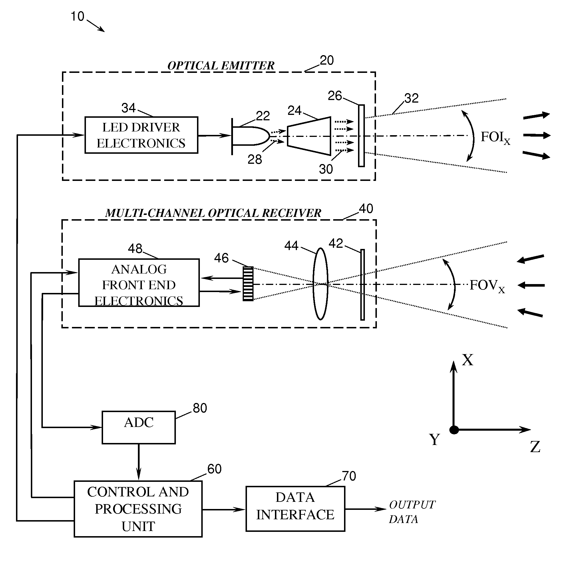
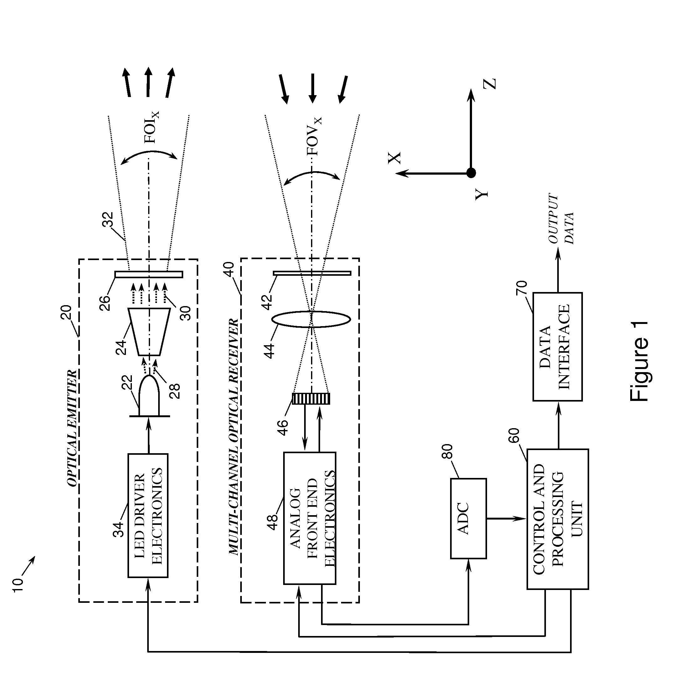
[0048]The general layout and key components / subsystems of a multiple-FOV scannerless optical rangefinder 10 according to an example embodiment of the present invention can be better appreciated by referring to the schematic diagram of FIG. 1. The optical rangefinder 10, which operates according to the pulsed TOF principle, comprises an optical emitter 20 that emits trains of optical pulses having predetermined temporal and spatial characteristics. It also includes a multi-channel optical receiver (shortened as MCOR) 40 for detection of the optical return signals and their subsequent conversion into electrical waveforms. Each detection channel of the MCOR 40 outputs return signal waveforms ...


PUM


Abstract

A multiple-field-of-view scannerless optical rangefinder operating in pulsed Time-Of-Flight operation for use in high ambient background light is described. The rangefinder comprises an optical emitter having a LED light source and driver electronics, emitting a train of light pulses having a broad field-of-illumination (FOI); a multi-channel optical receiver (MCOR) for detecting optical return signals, an overall field-of-view (FOV) encompassing each channel instantaneous FOV, the FOI encompassing the overall FOV, the multi-channel optical receiver having analog front-end electronics; an Analog-to-Digital Converter (ADC) for receiving and converting the waveforms into digital format; a control and processing unit (CPU) for generating a pulse trigger signal, sending a synchronization trigger signal to the MCOR for starting the detection of the optical return signals, and for processing the waveforms in digital format; a data interface; wherein a peak present in any of waveforms is a signature of an object located within the instantaneous FOV.

Description

TECHNICAL FIELD[0001]The present invention relates to an optical rangefinder system and method for use in various types of detection systems, and more particularly to a scannerless instrument for angularly-resolved detection and ranging of nearby objects and obstacles over a wide field of view which can operate in many light conditions including in full daylight.BACKGROUND OF THE ART[0002]Optical rangefinder instruments utilize either visible or invisible light for measuring the distance to a remote object. Over the years, these instruments have found their place in a host of applications, in particular in automotive and transportation applications where, for example, they are integrated in various types of active systems intended to assist vehicle drivers and to promote a higher safety on the road. Most optical rangefinders that range objects located beyond a few meters away operate according to the time-of-flight (TOF) principle, which relies on the finite propagation speed of lig...

Claims


Application Information

Patent Timeline
Patent Type & Authority Patents(United States)
IPC IPC(8): G01S7/486G01S17/93G01S17/10G01C3/08G01S7/4863G01S17/14G01S17/931
CPCG01C3/08G01S17/936G01S7/4863G01S17/105G01S17/42G01S17/14G01S17/931
Inventor MIMEAULT, YVAN
Owner LEDDARTECH INC
Why Eureka
Try Eureka