Controller for a power converter and a method of controlling a switch thereof

a technology of power converter and control board, applied in the direction of electric variable regulation, process and machine control, instruments, etc., can solve the problems of large inventory cost, unsatisfactory analog circuitry, complicated and expensive manufacturing process,

Inactive Publication Date: 2006-05-02
INTEL CORP
View PDF9 Cites 155 Cited by
  • Summary
  • Abstract
  • Description
  • Claims
  • Application Information

AI Technical Summary

Problems solved by technology

Analog circuitry, however, is undesirable for numerous reasons as set forth below.
First, analog controllers can require a multitude of interconnected discrete components to obtain a desired functionality of a single controller, which translates into large inventory costs, and more complicated and expensive manufacturing processes.
The analog controllers also tend to take up a fairly extensive footprint of the power converters to accommodate the numerous discrete components therein.
With a trend toward smaller power converters that parallels an increased level of integration with the loads powered thereby, employing a larger footprint for the controller necessitated by the numerous discrete components that are not easily reduced in size by circuit integration is disadvantageous.
Additionally, analog hardware is generally fixed and inflexible thereby making modifications thereto very difficult, if not impossible, without a complete redesign of the controller.
Analog circuitry is also subject to packaging and component defects, especially as the number of components increases, and analog circuitry tends to be sensitive to noise leading to further defects therein.
As is evident from the foregoing, analog controllers suffer from several drawbacks that inhibit the effectiveness thereof.
To date, however, controllers employing digital circuitry for use with power converters powering sensitive loads such as high performance microprocessors have not been viable alternatives to analog controllers due, in part, to a necessity for faster control loops and tighter budgetary constraints.
Cost effective digital signal processors are generally not capable of meeting the wide bandwidth requirements in the control loops to meet the fast transient response times and high switching frequencies of the power converters.
Moreover, overcoming the aforementioned limitations may induce cost prohibitive processor designs, when compared to the cost of analog controllers.
For instance, a 60 watt DC-to-DC power converter with analog control circuitry may cost around $35, whereas the cost of a digital signal processor alone for the power converter may cost around $15, which is a substantial cost for the control function by itself.
A controller incorporating a high performance digital signal processor has, in the past, been too expensive for use with the power converters when compared to the lower cost analog controller.
It is recognized that a significant contributor to a complexity of digital processing and the related computational delays in the digital processing of control signals is a substitution of digital circuitry in the controller for corresponding analog processes.
The process of analog to digital conversion, however, generally uses techniques such as “successive approximation” that employ a significant amount of time for iterative processing.
The aforementioned complexities all contribute either individually or in combination to the complexity of the controller employing digital circuitry.
Another significant contributor to a complexity of digital processing and the related computational delays in the digital processing of control signals is the signal processing necessary to produce a duty cycle for the switches of the power converter after the input signals are converted into a digital format.
Again, either circuit complexity with attendant cost for high performance circuitry or the computational delays of lower performance circuitry is a consequence of substituting digital processing for otherwise conventional analog processes.

Method used


Image

  • Controller for a power converter and a method of controlling a switch thereof
  • Controller for a power converter and a method of controlling a switch thereof
  • Controller for a power converter and a method of controlling a switch thereof

Examples


Embodiment Construction

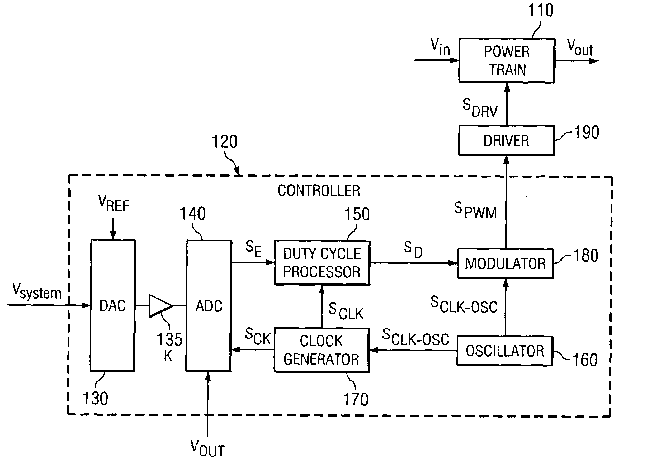
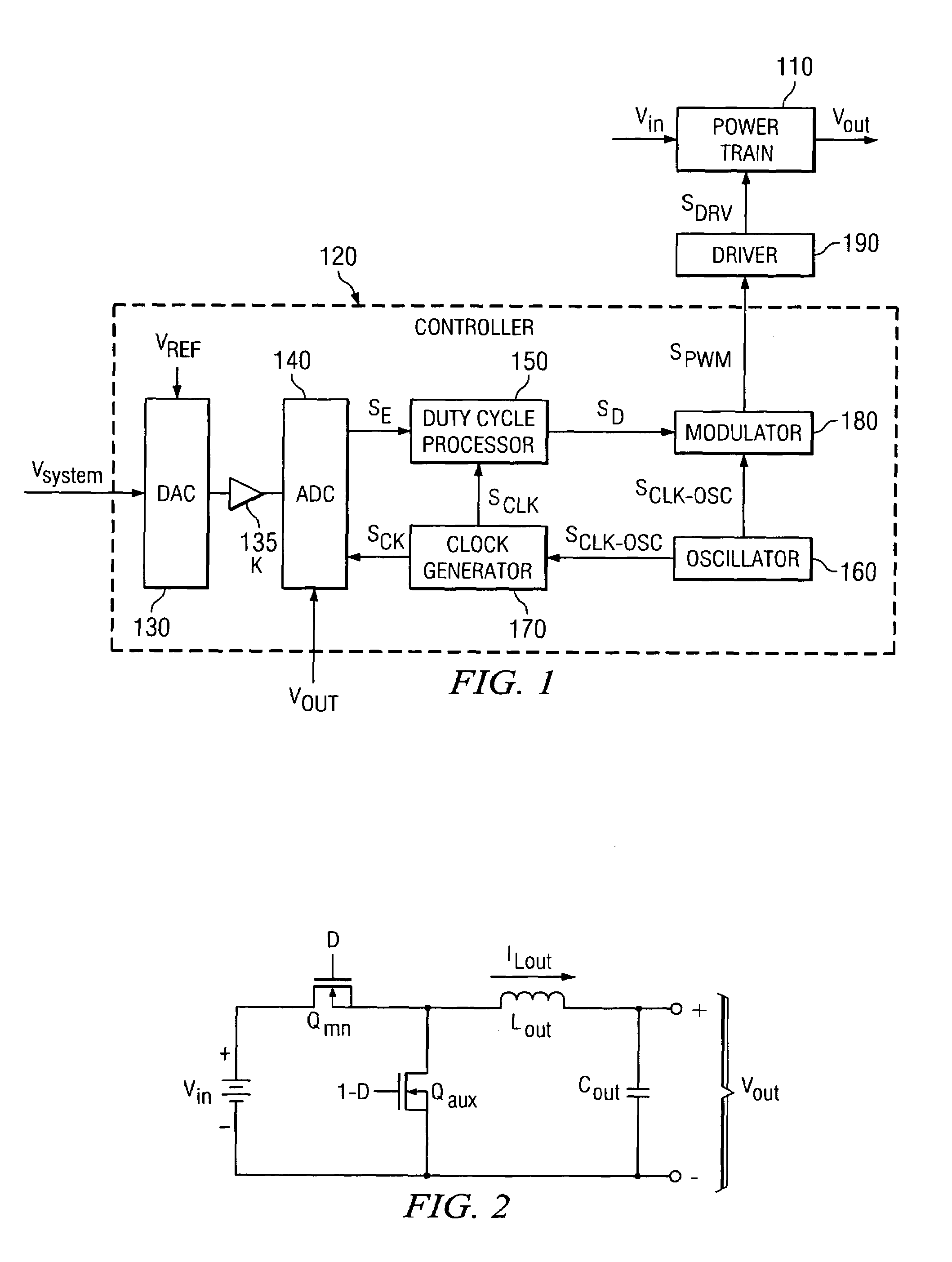
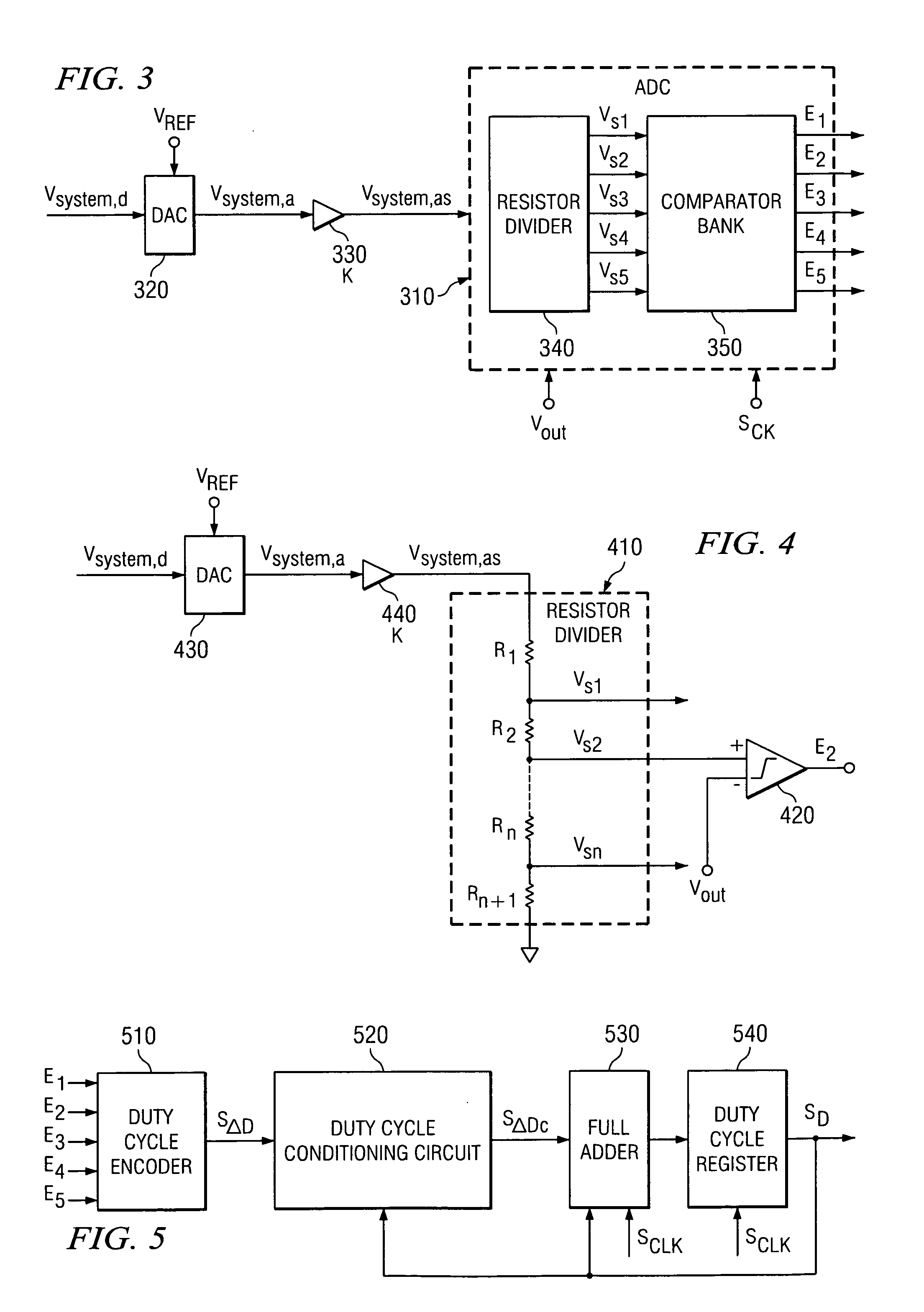
[0024]The making and using of the presently preferred embodiments are discussed in detail below. It should be appreciated, however, that the present invention provides many applicable inventive concepts that can be embodied in a wide variety of specific contexts. The specific embodiments discussed are merely illustrative of specific ways to make and use the invention, and do not limit the scope of the invention.

[0025]The present invention will be described with respect to preferred embodiments in a specific context, namely, a controller for a power converter, method of operation thereof and a power converter employing the same. The principles of the present invention, however, may also be applied to all types of power supplies employing various conversion topologies that may benefit from a controller employing digital circuitry. The advantages associated with the controller and power converter further exploit the benefits associated with the application of digital systems in electro...


PUM


Abstract

A controller for, related method of controlling a switch of, a power converter and a power converter employing the same. The controller is employable with a power converter including a switch of a power train configured to conduct for a duty cycle and provide a regulated output characteristic at an output thereof. In one embodiment, the controller includes a sparse analog-to-digital converter configured to determine a difference between the output characteristic and a desired characteristic and provide an error signal representing the difference in discrete steps. A magnitude of the discrete steps is small when the difference is small and the magnitude of the discrete steps is larger when the difference is larger. The controller also includes a duty cycle processor configured to provide a digital duty cycle signal to control the duty cycle of the switch as a function of the error signal.

Description

TECHNICAL FIELD[0001]The present invention is directed, in general, to power electronics and, more specifically, to a controller for a power converter, method of controlling a duty cycle of a switch of the power converter, and a power converter employing the same.BACKGROUND[0002]A switch mode power converter (also referred to as a “power converter”) is a power supply or power processing circuit that converts an input voltage waveform into a specified output voltage waveform. Controllers associated with the power converters manage an operation thereof by controlling the conduction periods of switches employed therein. Generally, the controllers are coupled between an input and output of the power converter in a feedback loop configuration (also referred to as a “control loop” or “closed control loop”).[0003]Typically, the controller measures an output characteristic (e.g., an output voltage) of the power converter and based thereon modifies a duty cycle of the switches of the power c...

Claims


Application Information

Patent Timeline
Patent Type & Authority Patents(United States)
IPC IPC(8): G05F1/40H02M3/157
CPCH02M3/157
Inventor DWARAKANATH, MIRMIRA RAMARAOWANG, JUEWESTON, HARRY THOMAS
Owner INTEL CORP
Why Eureka
Try Eureka