
Computer keyboard with quantitatively force-sensing keys

a keyboard and quantitative technology, applied in the field of computer keyboards, can solve the problems of difficult to reach keys, limited number of keys that can be added, and users may have difficulty remembering the purpose of all keys

Active Publication Date: 2005-03-17
MICROSOFT TECH LICENSING LLC
View PDF26 Cites 152 Cited by
  • Summary
  • Abstract
  • Description
  • Claims
  • Application Information

AI Technical Summary

Benefits of technology

The present invention addresses the above and other challenges associated with providing a keyboard with one or more force-sensing keys. In one embodiment, the invention includes a computer keyboard having a plurality of keys. Each of the keys has an unpressed condition in which a user is not exerting force on the key and a pressed condition in which the user is exerting force on the key. The keyboard further includes a force detection circuit configured to scan each key to determine if a scanned key is in a pressed condition. The force detection circuit quantifies, upon determining that a scanned key is in a pressed condition, the force exerted by a user on that pressed key. If a scanned key is not in a pressed condition, the force detection circuit proceeds to another key without attempting to determine a force exerted on an unpressed key.
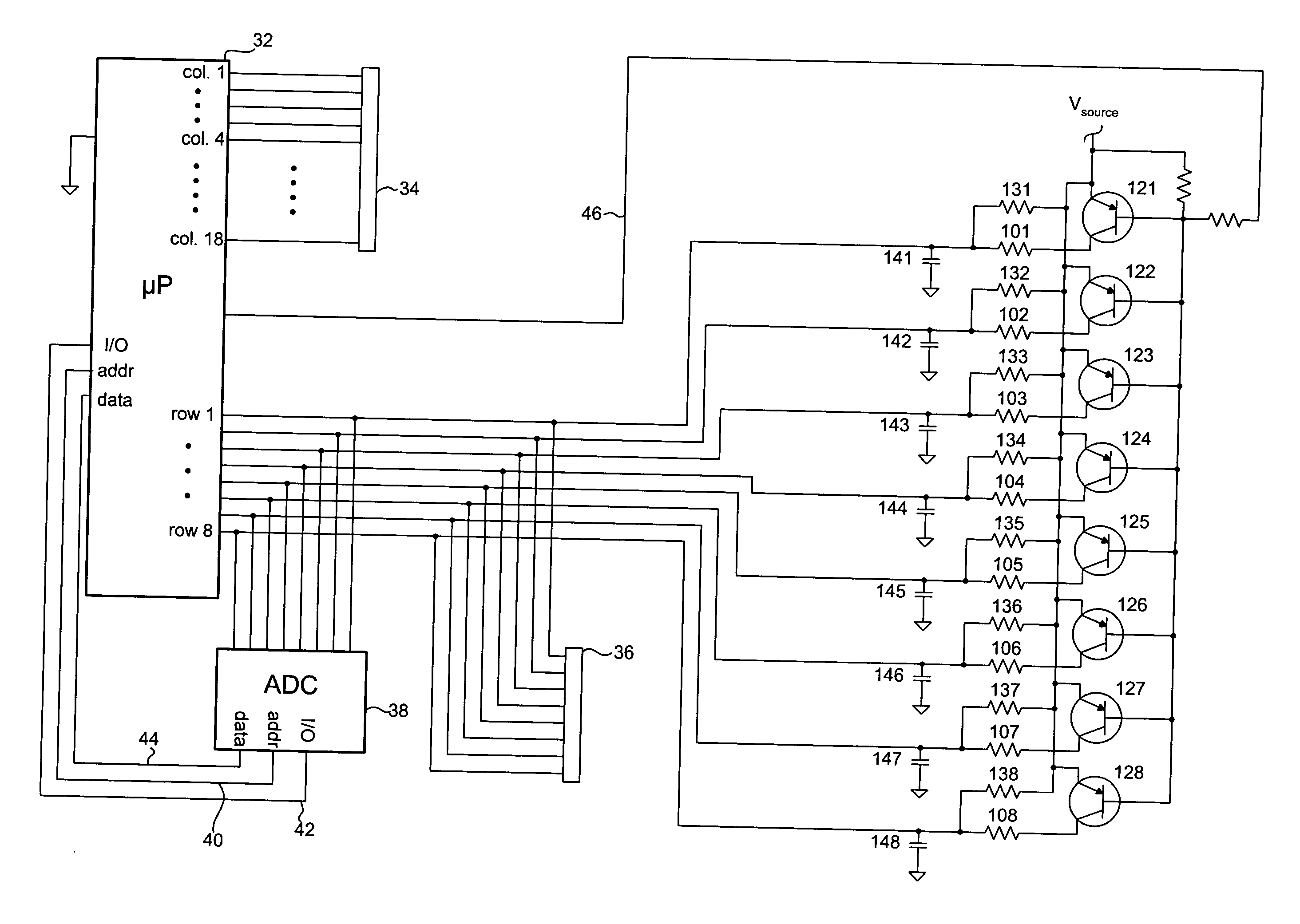
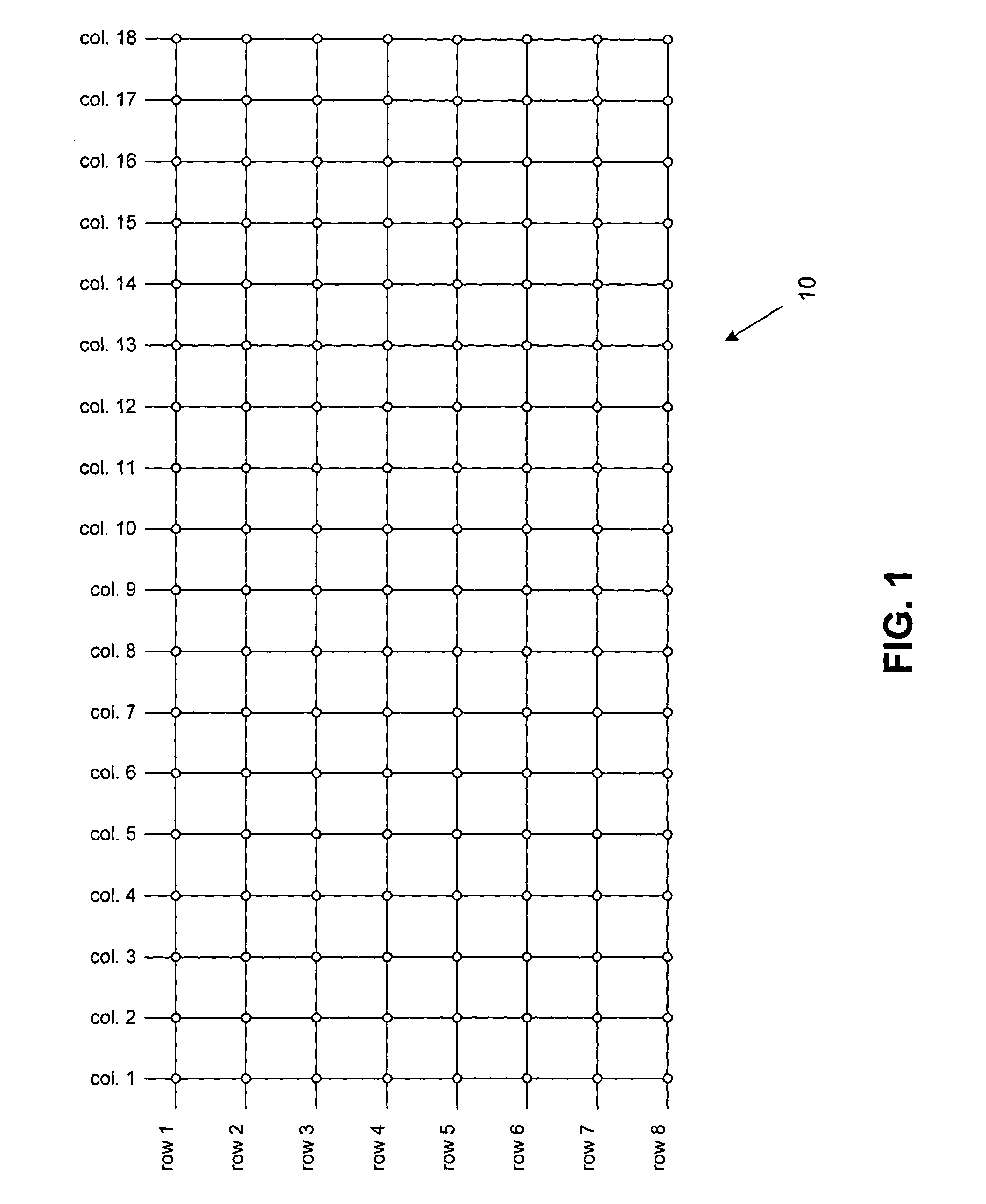
In another embodiment, the invention includes a computer keyboard having a grid of a first group of conductors and a second group of conductors. The first and second group conductors form a plurality of intersections. A force-sensitive resistor element is located at each intersection between the first and second group conductors forming the intersection. A plurality of keys are located above the intersections, each key being associated with an intersection and configured to exert force on the conductors and force-sensitive resistor element of the intersection during a key press. The keyboard further includes a microprocessor having a plurality of first group conductor pins, each pin being in contact with one of the first group conductors. The microprocessor also includes a plurality of second group conductor pins, each pin being in contact with one of the second group conductors. The keyboard additionally includes a sub-circuit connected to at least one of the second group conductors. The sub-circuit has a resistor network switchable by the microprocessor between a low resistance value and a high resistance value. Finally, the keyboard of this embodiment includes an Analog to Digital Converter (ADC) coupled to the sub-circuit and to the microprocessor. In other aspects, the microprocessor is configured to ground an individual conductor pin, to test another conductor pin for a threshold voltage level while the resistor network is switched to the high resistance value, to switch the resistor network to the low resistance value upon detecting the threshold voltage level on the tested conductor pin, and to receive from the ADC a digital value of a voltage on the tested conductor pin while the resistor network has the low resistance value.
These and other features and advantages of the present invention will be readily apparent and fully understood from the following detailed description of preferred embodiments, taken in connection with the appended drawings.

Problems solved by technology

There are practical limits on the number of keys that can be added, however.
If the keys become too numerous, some of the keys may be difficult to reach, and users may have difficulty remembering the purposes of all keys.
Although it is possible to add additional modifier keys so as to assign even more possible functions to existing keys, this also has practical limits.
Users are unlikely to remember all functions corresponding to all possible key combinations, and software developers are often unlikely to uniformly assign the same function to a particular key combination.
No known prior art has addressed many of the challenges such a keyboard presents.
Determining how hard a key has been pressed (as opposed to simply determining if the key is pressed or not pressed) requires additional processing, and thus additional time.
If each of the keys must be scanned to determine how hard a key may have been pressed, completing a scan could require an unacceptably long time.
Although using a higher speed processor is one possible solution, this can increase cost.

Method used


Image

  • Computer keyboard with quantitatively force-sensing keys
  • Computer keyboard with quantitatively force-sensing keys
  • Computer keyboard with quantitatively force-sensing keys

Examples


second embodiment

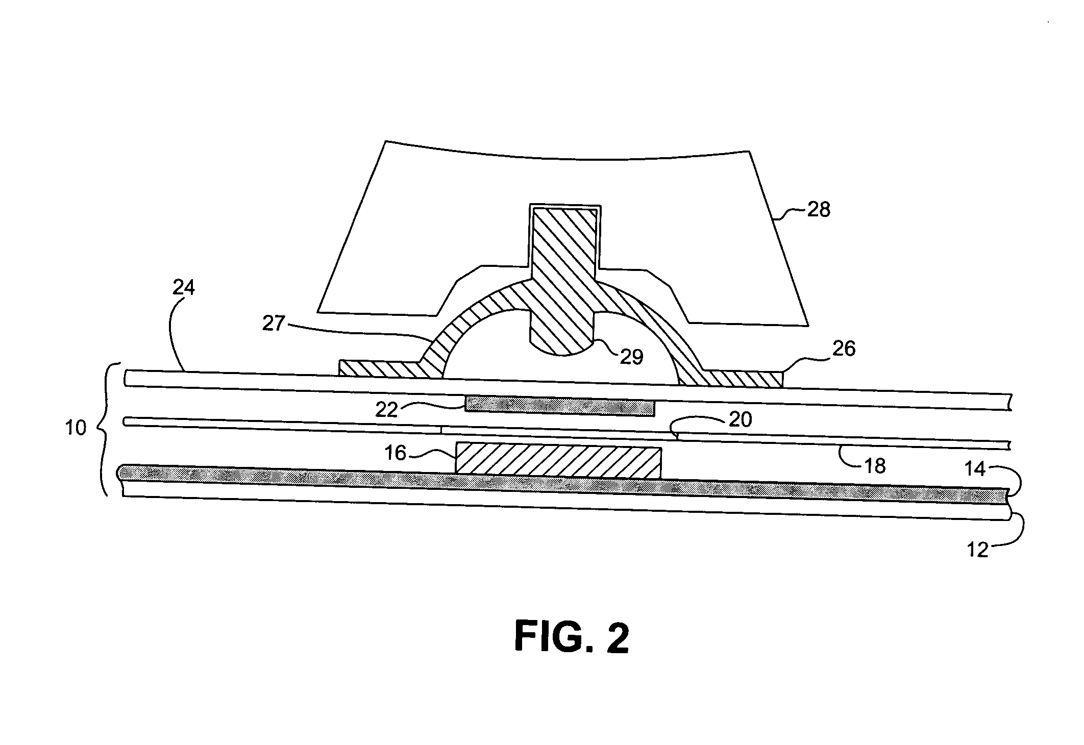
As shown in FIG. 10, a keyboard according to the invention also includes a grid 70 of row and column conductors. Grid 70 is supported by a frame 76. Placed over each row / column intersection of grid 70 is a dome switch 71 (only one dome switch shown) and a key 72. Dome switch 70 could be, e.g., similar to switch 26 (FIG. 2) or switch 26′ (FIG. 2A). Grid 70, frame 76 switches 71 and keys 72 form keyboard subassembly 73. When a user presses one of keys 72, the dome of the key's dome switch 71 causes an electrical connection to be formed between the row and column conductors over whose intersection the key and switch are positioned. Unlike grid 10 of FIG. 1, the row / column intersections of grid 70 do not include a FSR. Existing dome switches used in conventional keyboards can be employed.

Instead of detecting key force by measuring force at the level of the individual keys, the force upon a pressed key is determined by force sensors 74 supporting keyboard subassembly 73 on keyboard base...

first embodiment

Similar to the first embodiment, microprocessor 232 scans for a key press by selecting a row pin, grounding a column pin, testing the selected row pin for a low voltage, and then ungrounding the column pin and moving to the next column pin. After all column pins for a selected row pin have been tested, the next row pin is selected, and the process continues. Upon detecting a low voltage on a row pin, microprocessor 232 grounds pin 233. Force sensors 74 are only connected to ground when a key press is detected so as to avoid excessive power consumption by force sensors 74. Microprocessor 232 then sequentially addresses each force sensor 74 (via address line 240), sends a read signal via I / O clock line 242, and receives digital values for a voltage from each force sensor 74 via data line 244. The read values are then used as a force value for the pressed key. In other embodiments, the FSR 216 of one or more force sensors 74 could be coupled to an op amp instead of being used to form a...


PUM


Abstract

A computer keyboard has a grid of conductors forming a plurality of intersections, with force-sensitive resistor (FSR) elements located between the conductors at the intersections. A plurality of keys are located above the intersections and exert force on the conductors and FSR elements during key presses. A resistor network sub-circuit is connected to some of the conductors, and is switchable between low and high resistance values. An Analog to Digital Converter (ADC) is coupled to the resistor network sub-circuit. A microprocessor grounds a conductor and tests another conductor for a threshold voltage level while the resistor network is switched to the high resistance value. The microprocessor switches the resistor network to the low resistance value upon detecting the threshold voltage level and subsequently receives from the ADC a digital value of a voltage on the tested conductor.

Description

FIELD OF THE INVENTION This invention relates to computer keyboards. More specifically, this invention relates to computer keyboards having multiple keys capable of quantitatively sensing the force exerted upon those keys. BACKGROUND OF THE INVENTION As more and more uses are found for computers, and as existing uses are augmented and improved, it is often necessary to provide increasing amounts of input to computers. Numerous input mechanisms already exist, and additional mechanisms continue to be developed. For many purposes, however, the computer keyboard remains the primary computer input device. As such, there are numerous possible advantages to increasing the amount of data that a user can input to a computer via a keyboard. As used herein, “keyboard” includes, but is not limited to, “QWERTY” computer keyboards as described by, e.g., International Standard ISO / IEC 9995-1 and other standards. One manner of increasing the data which a keyboard can input is by increasing the n...

Claims


Application Information

Patent Timeline
Patent Type & Authority Applications(United States)
IPC IPC(8): G06F3/02G06F3/023
CPCG06F3/0233G06F3/0202
Inventor BATHICHE, STEVEN N.
Owner MICROSOFT TECH LICENSING LLC
Learn More