Imaging reader and method with dual function illumination light assembly

a reader and light assembly technology, applied in the field of imaging readers and methods with dual function illumination light assemblies, can solve the problems of difficult use of imaging readers, especially handheld movable readers, and the operator cannot see exactly whether a target is being targeted, so as to reduce the weight and size of readers and lighten the weight

Active Publication Date: 2014-12-16
SYMBOL TECH LLC
View PDF19 Cites 8 Cited by
  • Summary
  • Abstract
  • Description
  • Claims
  • Application Information

AI Technical Summary

Benefits of technology

[0013]Thus, a separate aiming light assembly, as taught by the prior art, has been eliminated, together with the associated expense of component cost and labor cost of assembling and aligning its various optical components, such as lasers, DOEs and ROEs. The elimination of a separate aiming light assembly reduces the weight and size of the reader, thereby rendering it very light in weight and compact, and particularly desirable for inclusion as a subsidiary system in an electrical apparatus, such as a price checker in a retail store, an airport gate check-in kiosk, a lottery machine, etc., that performs other functions.
[0014]In a preferred embodiment, the illumination light assembly includes at least one illumination light emitting diode (LED), and preferably a pair of illumination LEDs spaced apart from each other, and a pair of illumination lenses, one for each illumination LED, for optically modifying the illumination light as a pair of conical light beams that at least partially overlap on the target. Parallax from the two illumination LEDs will prevent the aforementioned cut-off from being perfect, but there will be a visible degradation in the intensity of the illumination light beyond the periphery of the field of view, which is sufficient to indicate where the field of view ends and to enable the operator to avoid positioning the target even partially outside the field of view. The illumination LEDs and the imager are commonly mounted on a printed circuit board, and the pair of illumination LEDs are preferably located at opposite sides of the imager.
[0015]The illumination light assembly could include an aiming LED for emitting an aiming light beam, and an aiming lens for optically modifying the aiming light beam to project an aiming spot centrally on the target. The aiming LED and the imager are commonly mounted on the printed circuit board, and the aiming LED is preferably located midway between the illumination LEDs. The aiming beam can also be used to wake up the reader after it has entered a sleep mode in which the illumination LEDs are turned off, but the aiming LED is turned on, and the imager is used to detect when the target is positioned in the aiming beam. In response to such detection, the controller turns the illumination LEDs 12A, 12B on, and target imaging resumes. The aiming beam provides sufficient light to wake up the reader even in dark, ambient environments.
[0016]Another feature of the present invention resides in a method of imaging targets with an imaging reader. The method is performed by bounding a passage with boundary walls of a housing, capturing return light from a target along an optical path through the passage over a field of view of a solid-state imager, generating an electrical signal indicative of the captured light, processing the electrical signal into data indicative of the target being imaged, projecting illumination light from an illumination light assembly along the optical path through the passage to illuminate the target, spacing the boundary walls along the optical path away from the imager and the illumination light assembly, and clipping the illumination light projected through the passage to form on the target an aiming light distribution that visually indicates a periphery of the field of view to assist in positioning the target entirely within the field of view.

Problems solved by technology

Yet, the use of the known imaging reader, especially a handheld movable reader, for imaging targets located anywhere within a range of working distances relative to the reader, has proven to be challenging.
An operator cannot see exactly whether a target is located entirely within the field of view of the array during reading, or know whether the target is optimally centrally located within the field of view.
It is not uncommon for the operator to repeatedly move the portable reader in multiple side-to-side, up-and-down, and back-and-forth, directions and repeatedly aim the portable reader at a single target several times before an indicator advises the operator that the target has been successfully imaged, thereby slowing down transaction processing and reducing productivity.
However, in most cases, this blind aiming at the target is difficult to overcome, especially when the position and orientation of the target are variable.
As advantageous as such known aiming light assemblies are, they have proven to be less than satisfactory in certain situations.
For example, the known aiming light assembly is expensive not only in terms of component cost, but also in the labor cost of assembling and aligning its various optical components.
The aiming light assembly adds non-negligible weight and size to the reader, which is undesirable for the reader whose size and weight are required to be low.

Method used


Image

  • Imaging reader and method with dual function illumination light assembly
  • Imaging reader and method with dual function illumination light assembly
  • Imaging reader and method with dual function illumination light assembly

Examples


Embodiment Construction

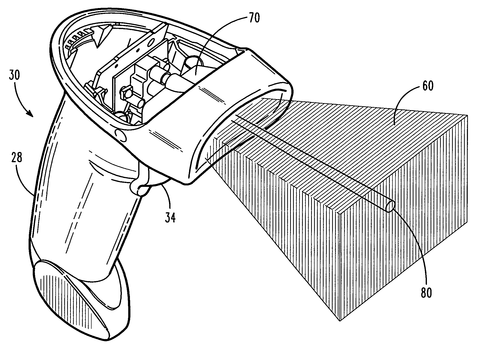
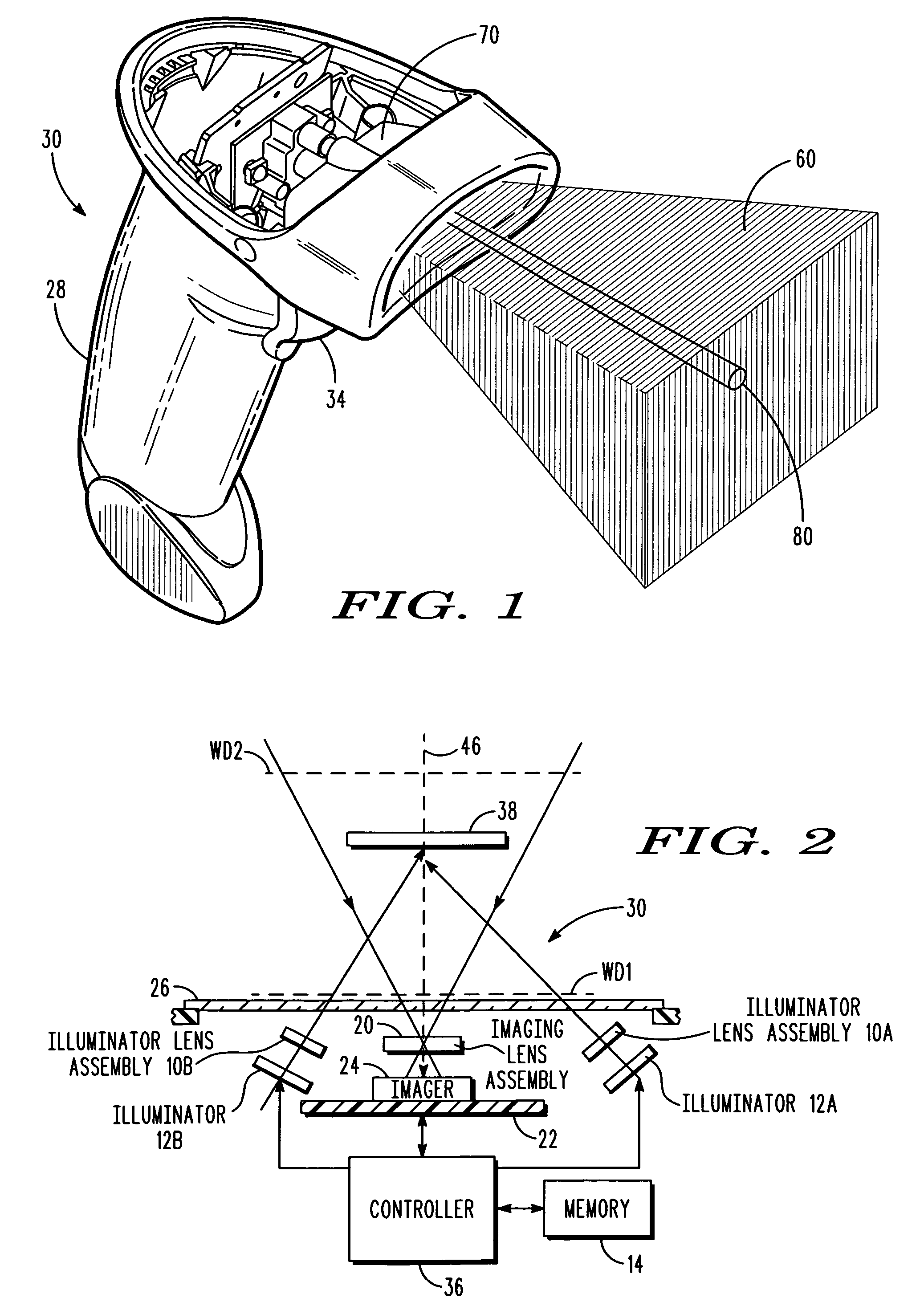
[0028]Reference numeral 30 in FIG. 1 generally identifies a portable, handheld imaging reader having a gun-shaped housing 28 and a light-transmissive window 26 (see FIG. 6) aimable at a target to be imaged. A trigger 34 is manually depressed by an operator to initiate imaging of targets, especially one- or two-dimensional symbols, and / or non-symbols, located at, or at a distance from, the window 26. Reference numeral 50 in FIG. 8 generally identifies a hands-free imaging reader having a light-transmissive window 52 and a box-shaped housing 54 supported by a base 56 for supporting the imaging reader 50 on a countertop or like support surface. The imaging reader 50 can thus be used as a stationary workstation in which targets are slid, swiped past, or presented to, the window 52, or can be picked up from the countertop and used as a handheld reader. Housings of other configurations can be employed. A data / power cable 58, as illustrated in FIG. 8, is connected to the reader 50, but can...


PUM


Abstract

An imaging reader for, and a method of, imaging targets, include a solid-state imager supported by a housing for capturing return light from a target over a field of view. An illumination light assembly performs both illumination and aiming functions. Illumination light is projected along an optical path through a passage in the housing to illuminate the target. The housing has boundary walls spaced along the optical path away from the imager and the illumination light assembly for clipping the illumination light projected through the passage to form on the target an aiming light distribution that visually indicates a periphery of the field of view to assist in positioning the target entirely within the field of view.

Description

DESCRIPTION OF THE RELATED ART[0001]Solid-state imaging systems or imaging readers have been used, in both handheld and hands-free modes of operation, to capture images from diverse targets, such as symbols to be electro-optically decoded and read and / or non-symbols to be processed for storage and display. Symbols include one-dimensional bar code symbols, particularly of the Universal Product Code (UPC) symbology, each having a linear row of bars and spaces spaced apart along a scan direction, as well as two-dimensional symbols, such as Code 49, a symbology that introduced the concept of vertically stacking a plurality of rows of bar and space patterns in a single symbol, as described in U.S. Pat. No. 4,794,239. Another two-dimensional code symbology for increasing the amount of data that can be represented or stored on a given amount of surface area is known as PDF417 and is described in U.S. Pat. No. 5,304,786. Non-symbol targets can include any person, place or thing, e.g., a sig...

Claims


Application Information

Patent Timeline
Patent Type & Authority Patents(United States)
IPC IPC(8): G06K7/10
CPCG06K7/10732G06K7/10831G06K2207/1011
Inventor BARKAN, EDWARDDRZYMALA, MARK
Owner SYMBOL TECH LLC
Why Eureka
Try Eureka