Waste collection system with controllers for regulating levels of vacuum drawn on a waste container

a waste container and vacuum controller technology, applied in the field of waste collection systems, can solve the problems of clutter, and the surgical personnel's utility, and reducing the extent to which the suction tubing is used

Active Publication Date: 2018-12-20
STRYKER CORP
View PDF0 Cites 6 Cited by
  • Summary
  • Abstract
  • Description
  • Claims
  • Application Information

AI Technical Summary

Benefits of technology

The patent is about a system that can be used in a hospital to collect and dispose of medical waste. The system consists of a mobile unit called the "rover" and a chassis that can hold the rover when it is not in use. When the rover needs to be emptied, it is connected to a "docking platform" and the waste is transferred to disposal lines. This system is designed to reduce the weight and size of the device that needs to be moved around, making it easier to position and route tubes and wires. The system also allows multiple rovers to be connected to the same chassis, which saves space and makes it easier to mop the floor. Additionally, the system can accommodate different size rovers that hold different amounts of waste.

Problems solved by technology

This reduces the extent to which the suction tubing, which invariably also functions as operating room clutter, is present around the surgical personnel.
There are some limitations that diminish their utility.
First, because the suction pump is mounted to the mobile unit, where limited space is available for noise abatement materials and treatment methods, higher than desired noise levels may be present in close proximity to the surgical area.
The weight of the mobile unit, with the containers filled close to capacity can be difficult for some medical personnel to move between the surgical location or operating room and the docking station.

Method used


Image

  • Waste collection system with controllers for regulating levels of vacuum drawn on a waste container
  • Waste collection system with controllers for regulating levels of vacuum drawn on a waste container
  • Waste collection system with controllers for regulating levels of vacuum drawn on a waste container

Examples


first embodiment

II. First Embodiment

[0076]A. Mobile Chassis

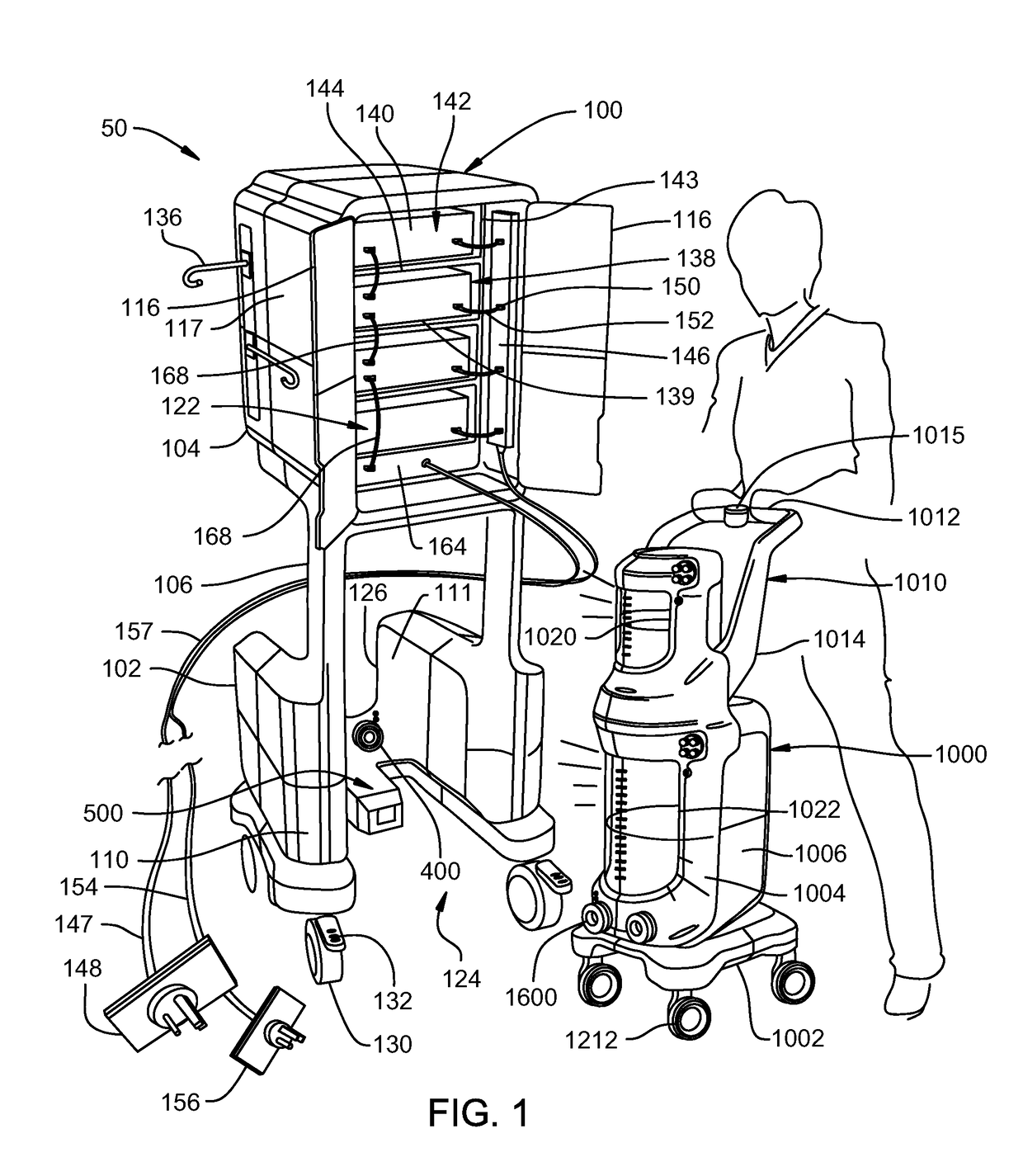
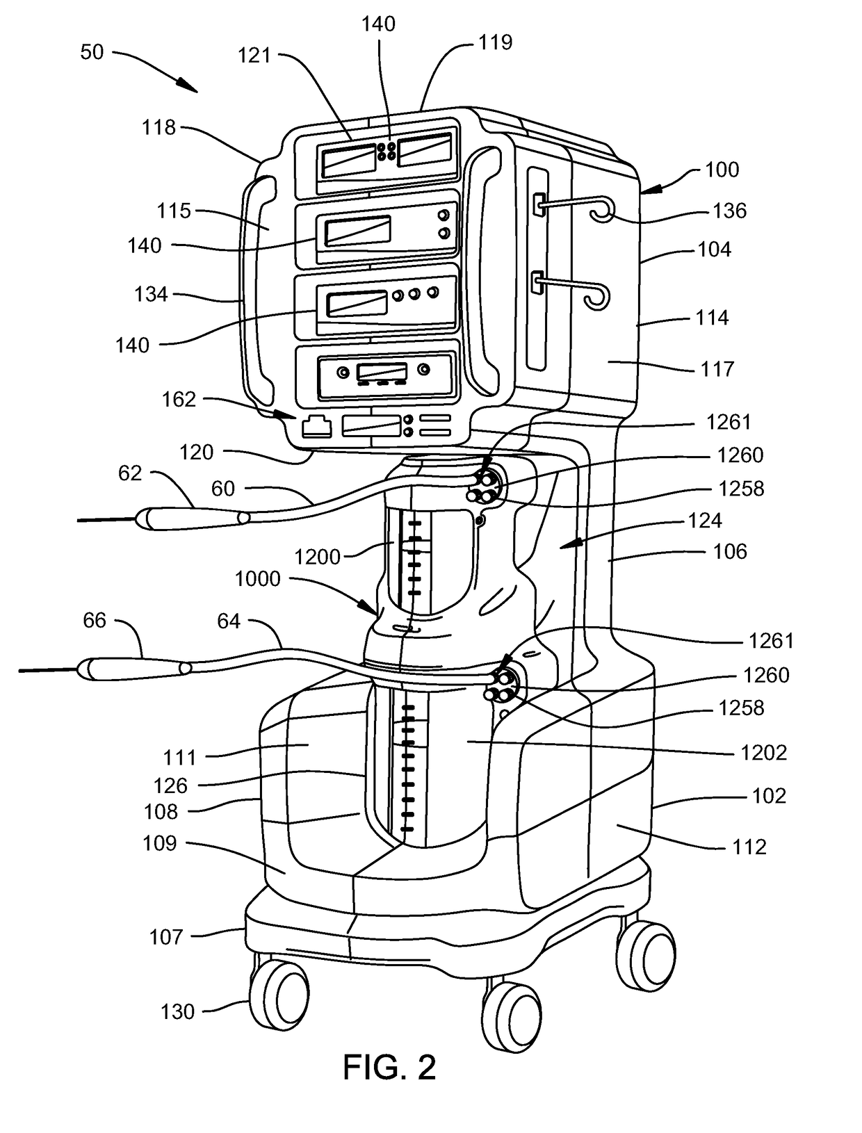
[0077]Turning to FIGS. 1 and 2, mobile chassis 100 of the first embodiment of this invention is illustrated. Mobile chassis 100 comprises a generally rectangular lower chassis 102 and a generally rectangular upper chassis 104. Upper chassis 104 is supported above lower chassis 102 by a pair of spaced apart supports 106. Lower chassis 102 has outer covers 107 and 108. Outer cover 108 includes a U-shaped front panel 109, rear panels 110, inner panels 111 and outer panels 112. Upper chassis 104 has an outer cover 114 that includes a front panel 115, a pair of rear doors 116, side panels 117, 118, top panel 119 and bottom panel 120. Front panel 115 has several rectangular shaped openings 121. An interior cavity 122 is defined within upper chassis 104.

[0078]Covers 107, 108, 114 and doors 116 can be formed from injection molded plastic or other suitable materials and are attached to lower chassis 102 and upper chassis 104 by suitable methods such...

second embodiment

III. Second Embodiment

[0195]FIG. 25 illustrates an alternative embodiment of a medical / surgical waste collection system 2000 constructed in accordance with the present invention. Waste collection system 2000 comprises a mobile chassis 2100 and a mobile rover 2500. Mobile rover 2500 is the same as described in the first embodiment except that the shapes and sizes of some of the exterior components have been changed. The internal components and operation of mobile rover 2500 are the same as for mobile rover 1000. Mobile chassis 2100 is sometimes called a suction cart 2100. Mobile rover 2500 is sometimes called a container cart 2500.

[0196]Mobile chassis 2100 is similar to mobile chassis 100 of the first embodiment except that the upper chassis 104 (FIG. 1) has been omitted. Mobile chassis 2100 is generally rectangular in shape and includes a generally planar top cover 2104 that extends over four outer side walls 2106 of mobile chassis 2100. Handles 2108 are attached to one or more wall...

third embodiment

IV. Third Embodiment

[0197]A. Mobile Chassis

[0198]Turning to FIGS. 26 and 28, waste collection system 3000 includes a chassis 3100 and a mobile rover 4000. Rover 4000 can be mated with the chassis 3100. Chassis 3100 is sometimes called a suction cart 3100. Mobile rover 4000 is sometimes called a container cart 4000. With specific reference to FIG. 26, chassis 3100 is generally rectangular in shape and has a lower chassis 3102 and an upper chassis 3104. Chassis 3100 has an inner frame that supports several outer molded covers 3108. Covers 3108 include front panel 3109, rear panel 3110, side panels 3111 and top panel 3112.

[0199]Covers 3108 can be formed from molded plastic and attached to lower chassis 3102 and upper chassis 3104 by suitable methods such as through the use of fasteners. Covers 3108 are used to protect the internal components of chassis 3100 and to provide improved visual aesthetics. A receptacle or void space 3124 is defined in front panel 3109. Void space 3124 receive...


PUM


Abstract

A waste collection system for collecting medical / surgical waste. A mobile rover includes at least one waste container supported on the mobile rover for storing the medical / surgical waste. A chassis is separate from and configured be removably coupled with the mobile rover. The chassis supports a chassis controller and a vacuum pump configured to draw a vacuum on the waste container. A rover controller is supported on the mobile rover and configured to receive a pressure signal representative of a level of the vacuum. The chassis controller is configured to be in communication with the rover controller and to regulate the level of the vacuum drawn based on the pressure signal. A transmitter may be supported on the mobile rover and in communication with the rover controller, and a receiver may be supported on the chassis to be in communication with the transmitter to establish a communication circuit for data transfer.

Description

CROSS REFERENCE TO RELATED APPLICATIONS[0001]This application is a continuation of and claims priority to and through co-pending U.S. patent application Ser. No. 14 / 691,613, filed on Apr. 21, 2015, which is a continuation of Patent Cooperation Treaty Appl. No. PCT / US2013 / 066101, filed on Oct. 22, 2013, which claims priority to and all the benefits of U.S. Provisional Patent Appl. No. 61 / 717,793, filed on Oct. 24, 2012. The entire contents of the aforementioned applications are hereby incorporated by reference.FIELD OF THE INVENTION[0002]This invention relates generally to waste collection systems for the collection of medical waste generated during medical and surgical procedures. More particularly, this invention relates to a waste collection system that is easily transportable within a surgical facility and that can hold a large volume of medical waste.BACKGROUND OF THE INVENTION[0003]A byproduct of the performance of some medical and surgical procedures is the generation of liqui...

Claims


Application Information

Patent Timeline
Patent Type & Authority Applications(United States)
IPC IPC(8): A61M1/00A61B50/10A61B50/13A61B5/00A61B17/00A61M39/10
CPCA61B2560/0437A61M1/0031A61M1/0023A61B17/00A61B2017/00017A61B2217/005A61B2217/007A61M2205/52A61M1/0003A61M39/10A61M2205/0272A61M2205/05A61M2205/3331A61M2205/3576A61B50/13A61B50/10A61M1/0005A61M1/0001A61M1/0052A61M2209/084A61B5/6887A61M1/63A61M1/784A61M1/74A61M1/79A61M1/782A61M1/60A61M1/77A61M1/73A61M1/743
Inventor REASONER, STEPHEN J.HENNIGES, BRUCECARUSILLO, STEVENMACLACHLAN, BRIAN
Owner STRYKER CORP
Why Eureka
Try Eureka