Method of manufacture of an energy absorbing tire cage

a cage and energy-absorbing technology, applied in the field of cage tires, can solve the problems of high speed, high cost, and high risk of split rim tires, and achieve the effect of reducing weight and size of the tire cage and being cost-effectiv

Inactive Publication Date: 2009-07-09
GOLDCORP CANADA
View PDF38 Cites 0 Cited by
  • Summary
  • Abstract
  • Description
  • Claims
  • Application Information

AI Technical Summary

Benefits of technology

[0009]To provide the above transportability features and to additionally provide a more cost effective tire cage for large tires than heretofore possible, it is an aspect of the present invention to use a light weight energy absorbing material such as an energy absorbing metallic foam to cushion the frame of the present tire cage from being damaged by high velocity portions of an exploding tire, and particular, portions of a split rim. The use of such energy absorbing foam

Problems solved by technology

It is well known that inflation or deflation of certain tires can be hazardous to personnel performing such operations and to others nearby.
In particular, split rim tires are known to be especially dangerous in that metal portions of the split rim can be propelled at high velocity if the tire fails.
Moreover, such tire failures where portions of the split rim may become projectiles is especially dangerous when inflating or deflating such tires.
However, for inflation or

Method used


Image

  • Method of manufacture of an energy absorbing tire cage
  • Method of manufacture of an energy absorbing tire cage
  • Method of manufacture of an energy absorbing tire cage

Examples


Embodiment Construction

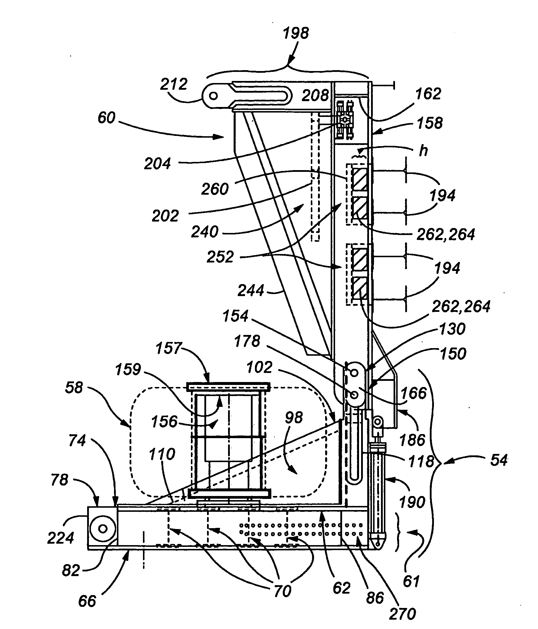
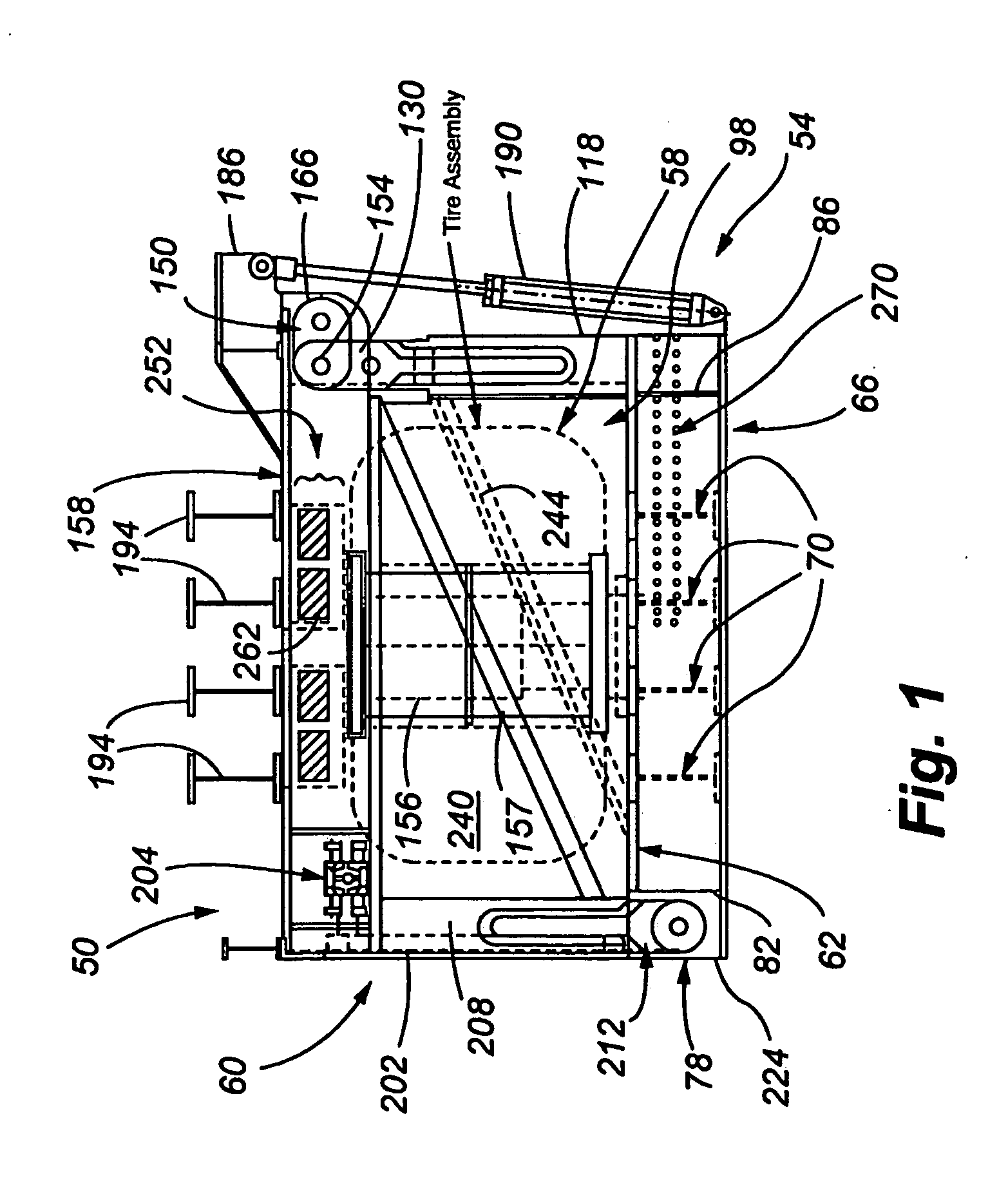
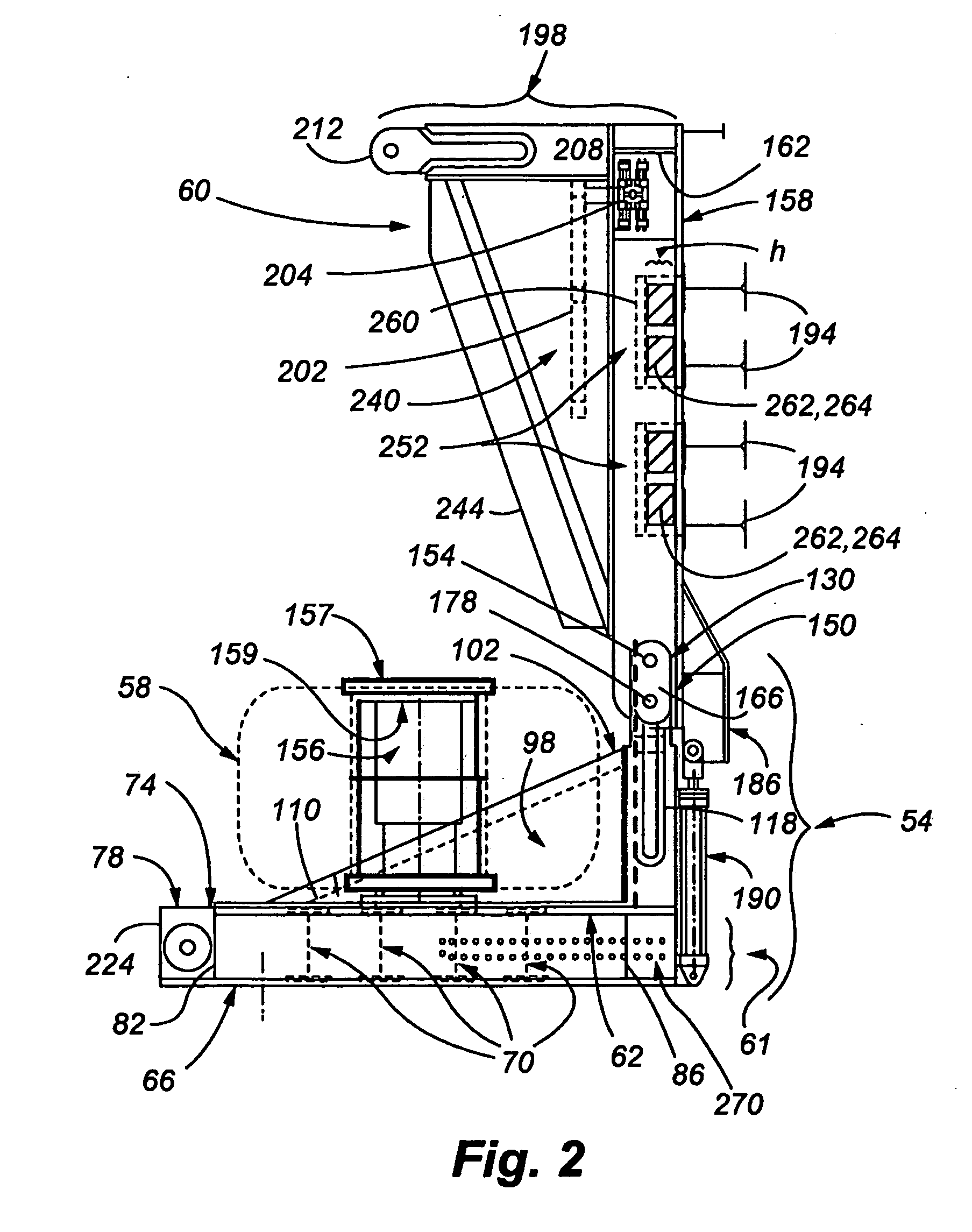
[0025]The embodiments of the tire cage 50 illustrated in FIGS. 1-11, and described hereinbelow are particularly suitable for safely containing an explosion of a conventional heavy equipment 8 foot diameter tire, i.e., suitable for safely containing an explosive impact force of up to 3500 to 3700 kiloNewtons (kN) and 1160 kilojoules (kJ) of energy. Accordingly, for safely containing an explosion of a tire of a smaller or larger tire (more particularly, an explosion of a tire storing a substantially larger or smaller amount of energy) certain of the tire cage structural members described herein below, and the forces these members need to withstand may be substantially different from the dimensions provided herein. However, one of ordinary skill in the art will, from the description herein, be able to construct an embodiment of the tire cage 50 for such smaller or larger tires, bearing in mind that, in general, the energy stored in a tire exponentially increases with the diameter of th...


PUM

PropertyMeasurementUnit
Pressureaaaaaaaaaa
Pressureaaaaaaaaaa
Diameteraaaaaaaaaa

Abstract

A tire cage is disclosed for containing the debris from a tire explosion. The cage includes a lightweight energy absorbing material for protecting structural members of the cage from tire explosion damage so that the cage is reusable. The energy absorbing material may be a metallic foam or other open celled structured material that is able to absorb large amounts of kinetic energy by permanently deforming. The cage is particularly effective in containing explosions of large equipment tires 6 to 12 feet in diameter and having a stored kinetic energy in a range of approximately 900 kilojoules to 1500 kilojoules.

Description

RELATED APPLICATION[0001]The present application is a continuation of U.S. patent application Ser. No. 11 / 695,962, filed Apr. 3, 2007, entitled “METHOD OF MANUFACTURE OF AN ENERGY ABSORBING TIRE CAGE”, which is a divisional of U.S. patent application Ser. No. 10 / 971,819, filed Oct. 21, 2004, now U.S. Pat. No. 7,240,713 entitled “ENERGY ABSORBING TIRE CAGE AND METHOD OF USE”, each of the above-identified applications fully incorporated by reference herein.RELATED FIELD OF THE INVENTION[0002]The present invention relates to a cage tire for containing tire explosions, and in particular, to tire cages for containing tire explosions of having a diameter in the range of 6 to 12 feet, and having stored energy, e.g., in a range of 500 kilojoules to 7500 kilojoules which is approximately 13-200 times the energy of a conventional truck / SUV tire.BACKGROUND[0003]It is well known that inflation or deflation of certain tires can be hazardous to personnel performing such operations and to others n...

Claims


Application Information

Patent Timeline
IPC IPC(8): B23P11/00
CPCY10T29/49826B60C25/147
Inventor MUNROE, SCOTT TROYWILSON, DONALD KENT
Owner GOLDCORP CANADA
Why Eureka
Try Eureka