Cage for thrust roller bearing

a technology of thrust roller bearing and cage, which is applied in the direction of rolling contact bearings, shafts and bearings, rotary bearings, etc., can solve the problem of lower radial load bearing capacity of the above-described thrust cage, and achieve the effect of enhancing the stiffness of the cage against radial compressive loads

Inactive Publication Date: 2014-12-16
JTEKT CORP
View PDF2 Cites 2 Cited by
  • Summary
  • Abstract
  • Description
  • Claims
  • Application Information

AI Technical Summary

Benefits of technology

[0008]One object of the invention is to provide a cage for a thrust roller bearing, configured such that local deformation of the cage, which is caused by holding the cage between an inner ring and an outer ring, is suppressed and the stiffness of the cage against a radial compressive load is enhanced, while the roller retaining capability of the cage is appropriately maintained.

Problems solved by technology

However, because the cage bars of the above-described thrust cage are bent into a generally U-shape in the axial direction, the radial load bearing capacity of the above-described thrust cage is lower than that of a thrust cage having cage bars that are not bent.

Method used


Image

  • Cage for thrust roller bearing
  • Cage for thrust roller bearing
  • Cage for thrust roller bearing

Examples


first embodiment

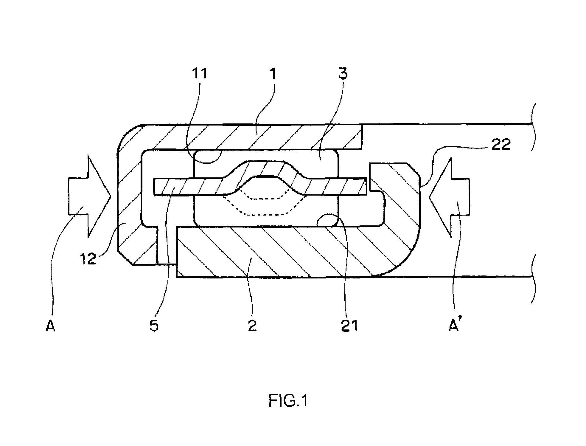
[0018]FIG. 1 is a schematic sectional view illustrating a thrust cylindrical roller bearing according to the invention, taken along the radial direction of the thrust cylindrical roller bearing.

[0019]The thrust cylindrical roller bearing includes an outer ring 1, an inner ring 2, a plurality of cylindrical rollers 3 and a cage 5 for a thrust cylindrical roller bearing (hereinafter, simply referred to as “thrust cage”). The outer ring 1 has a disc shape, and has a flat raceway surface 11. Further, the outer ring 1 has a bent extended portion 12. The bent extended portion 12 is located at a radially outer end portion of the outer ring 1. The bent extended portion 12 has a shape formed by bending a radially outer end portion of the outer ring 1 toward one side in the axial direction and is then extended along the axial direction toward the one side in the axial direction.

[0020]The inner ring 2 has a disc shape, and has a flat raceway surface 21. The raceway surface 21 of the inner ring...

second embodiment

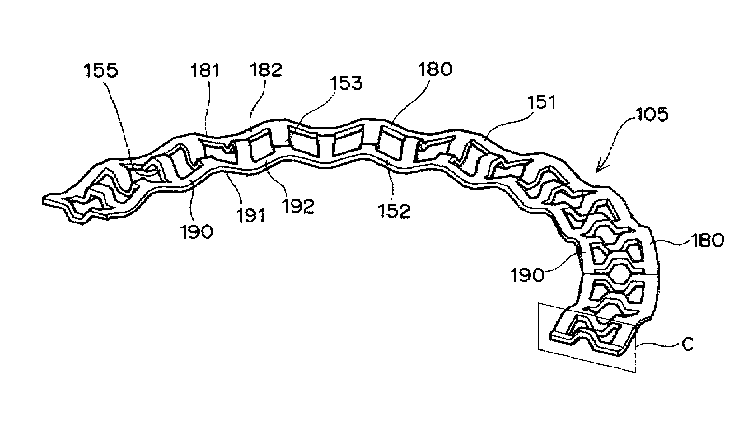
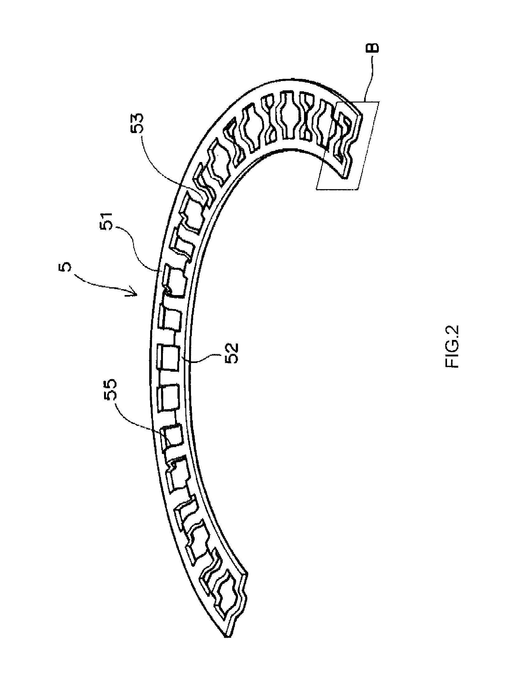
[0039]FIG. 5 is a view corresponding to FIG. 2 and illustrating a thrust cage 105 according to the invention.

[0040]The thrust cage 105 in the second embodiment has an even number of pockets 155, like the thrust cage 5 in the first embodiment. The thrust cage 105 in the second embodiment differs from the thrust cage 5 in the first embodiment, in that a large-diameter annular portion 151 and a small-diameter annular portion 152 are both corrugated in a cycle of the same phase angle. In the second embodiment, descriptions on the same structures as those in the first embodiment, such as the structure that cage bars 153 have recessed portions, will be omitted, and the advantageous effects as those in the first embodiment will also be omitted. Further, in the second embodiment, descriptions on the same modified examples as those in the first embodiments will also be omitted.

[0041]The thrust cage 105 in the second embodiment is made of a steel material that is can be press-formed, and is f...


PUM


Abstract

A cage bar of at least one of pockets, the cage bar being on one side of the at least one of the pockets in the circumferential direction, has a bent portion that is bent toward one side in an axial direction such that an end face of the cage bar on the other side in the axial direction is recessed toward the one side in the axial direction. Further, a cage bar of the at least one of the pockets, the cage bar being on the other side of the at least one of the pockets in the circumferential direction, has a bent portion that is bent toward the other side in the axial direction such that an end face of the cage bar on the one side in the axial direction is recessed toward the other side in the axial direction.

Description

INCORPORATION BY REFERENCE[0001]The disclosure of Japanese Patent Application No. 2012-245542 filed on Nov. 7, 2012 including the specification, drawings and abstract, is incorporated herein by reference in its entirety.BACKGROUND OF THE INVENTION[0002]1. Field of the Invention[0003]The invention relates to a cage for a thrust roller bearing.[0004]2. Description of Related Art[0005]A conventional cage for a thrust roller bearing (hereinafter, simply referred to as “thrust cage”) is described in, for example, Japanese Patent Application Publication No. 2008-202797 (JP 2008-202797 A). The thrust cage has a large-diameter annular portion, a small-diameter annular portion and a plurality of cage bars. The large-diameter annular portion and the small-diameter annular portion are concentric with each other, and are located on substantially the same plane. The cage bars connect the large-diameter annular portion and the small-diameter annular portion to each other. The cage bars are arrang...

Claims


Application Information

Patent Timeline
Patent Type & Authority Patents(United States)
IPC IPC(8): F16C33/54F16C33/46
CPCF16C19/305F16C33/541F16C33/4676F16C33/546F16C33/4682
Inventor ONIZUKA, TAKAAKI
Owner JTEKT CORP
Why Eureka
Try Eureka