Double break disconnect switch

a technology of disconnect switch and switch, applied in the field of double break disconnect switch, to achieve the effect of reducing wear

Active Publication Date: 2014-12-23
CLEAVELANDPRICE ENTERPRISES
View PDF7 Cites 8 Cited by
  • Summary
  • Abstract
  • Description
  • Claims
  • Application Information

AI Technical Summary

Benefits of technology

[0008]The slot provides a helical course for the blade guide pin to ride on the camming surface. The vertical plate extension is twisted transversely for providing the slot with a predetermined angle and a helical course for the camming surface to minimize the wear between the guide pin and the camming surface.

Problems solved by technology

Because of restrictions to movement that may develop because of causes such as ice build up between the fixed jaws and the switch blade assembly or debris large forces are often necessary to initially open or finally close the switch.

Method used


Image

  • Double break disconnect switch
  • Double break disconnect switch
  • Double break disconnect switch

Examples


Embodiment Construction

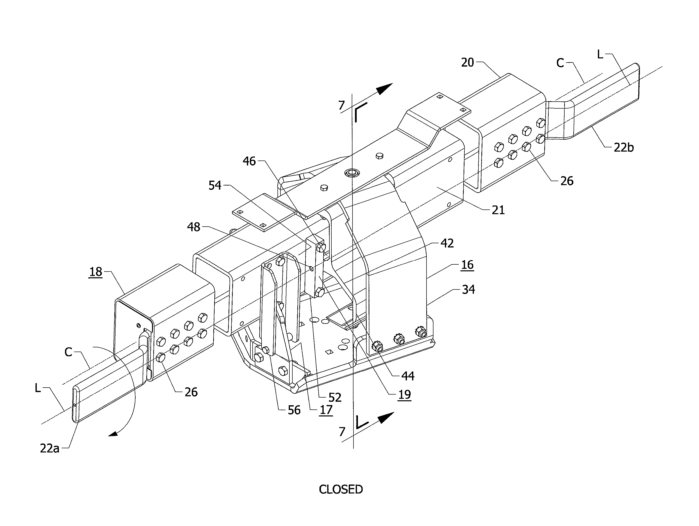
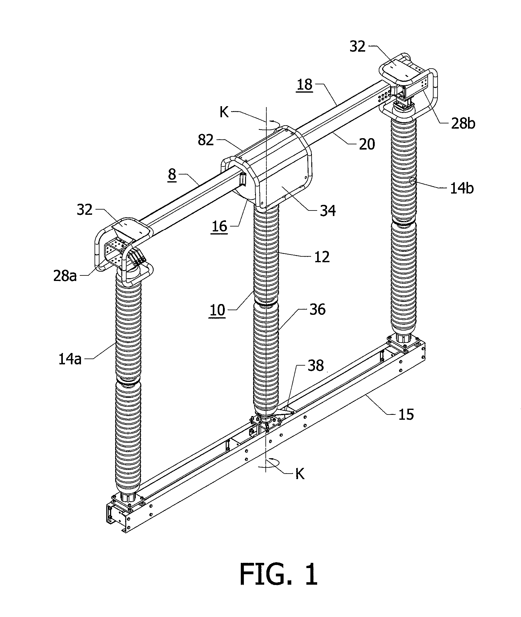
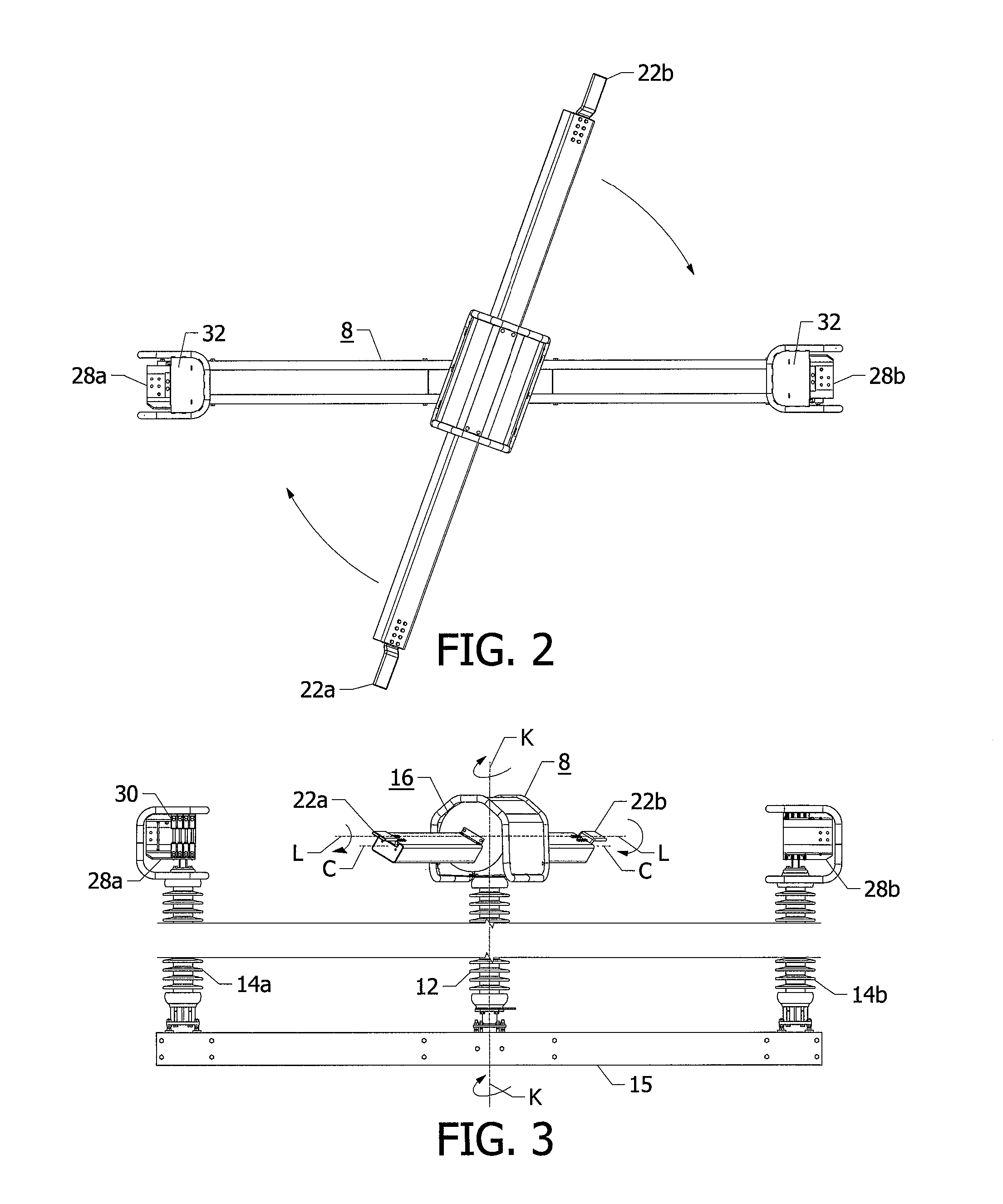
[0020]With reference to FIGS. 1-7, a double break disconnect switch 8 is shown comprising a drive arrangement 10 which includes a rotatable support assembly 36 including center rotatable insulator 12 and fixed insulators 14a, 14b and a lever 38 mounted to a base member 15. The supporting structure which includes the center rotatable insulator 12 and the fixed insulators 14a, 14b may be arranged as shown in FIG. 1 or may be in a split V configuration, not shown, for example. A bearing arrangement 16 is mounted on the drive arrangement 10 on the top of the rotatable insulator 12. The drive arrangement 10 is in relative movement relationship with respect to the bearing arrangement 16 via the lever 38. A switch blade assembly 18 includes a tubular switch blade 20 which may have a rectangular shape and be made of aluminum, for example. In FIGS. 4 and 5, the switch blade 20 has contact terminals 22 attached to its ends. The switch blade 20 is heavy and may weigh 120 pounds and be 13 feet ...


PUM


Abstract

A double break disconnect switch with a novel drive mechanism that swings the blade open and closed in a conventional manner but the rotation with respect to its longitudinal axis is unique. This mechanism uses a unique cam to rotate the blade about a hinge axis. The blade bearings are of very small diameter to reduce friction and are offset from the blade center of gravity so as to use the blade's weight to keep the blade in disengagement with the break jaw contacts when the switch is opened. The blade bearings are not around the diameter of the blade, the friction does not increase as current rating increases. A camming mechanism is profiled to give maximum rotational torque to the blade as it compresses the contact fingers as the switch closes to its final position.

Description

BACKGROUND OF THE INVENTION[0001]The invention relates generally to a double break disconnect switch for high voltage applications and, more particularly, to a double break disconnect switch having fixed jaws and a switch blade assembly having a macro swinging movement relative to the jaws and arranged for a rotational movement with respect to its longitudinal axis upon contact with the fixed jaws to effect closing and opening of the switch.[0002]High voltage switches of this type customarily employ round tubular blades which rotate on their long center axis to achieve the contact pressure developing or relieving for opening or closing of the switch. Because of restrictions to movement that may develop because of causes such as ice build up between the fixed jaws and the switch blade assembly or debris large forces are often necessary to initially open or finally close the switch.[0003]Many such switches on the market today, employ arrangements such as a beveled gear approach for ro...

Claims


Application Information

Patent Timeline
Patent Type & Authority Patents(United States)
IPC IPC(8): H01H31/30
CPCH01H31/20H01H1/48
Inventor KOWALIK, PETER, M.
Owner CLEAVELANDPRICE ENTERPRISES
Why Eureka
Try Eureka