Swivel mop with revolving dehydration function

a technology of revolving dehydration and swivel mop, which is applied in the field of swivel mop, can solve the problems of increasing the cost of fabrication, increasing the cost of packaging, storage and transportation, and so as to reduce the cost of fabrication and packaging. , the effect of shortening the expansion of cloth strips

Inactive Publication Date: 2015-01-06
SHIH CHIN YANG
View PDF3 Cites 4 Cited by
  • Summary
  • Abstract
  • Description
  • Claims
  • Application Information

AI Technical Summary

Benefits of technology

[0007]According to the primary advantage of the present invention, when the second rotation disk is rotated by the inner post, the linking cords are driven by the second rotation disk to drive the cloth strips toward the central portion of the second rotation disk so that the cloth strips are gathered toward the central portion of the second rotation disk to limit and shorten the extent of expansion of the cloth strips during the swivel dehydration process, thereby facilitating a user dehydrating the cloth strips.
[0008]According to another advantage of the present invention, the cloth strips have a smaller extent of expansion during rotation so that the cloth strips can be dehydrated in a basket with a normal size, thereby greatly decreasing the cost of fabrication, packaging, storage and transportation of the swivel mop.
[0009]Further benefits and advantages of the present invention will become apparent after a careful reading of the detailed description with appropriate reference to the accompanying drawings.BRIEF DESCRIPTION OF THE SEVERAL VIEWS OF THE DRAWING(S)
[0010]FIG. 1 is a front view of a swivel mop in accordance with the preferred embodiment of the present invention.
[0011]FIG. 2 is a schematic operational view of the swivel mop as shown in FIG. 1 in use.
[0012]FIG. 3 is a partially exploded perspective view of the swivel mop as shown in FIG. 1.

Problems solved by technology

However, the mop head is placed in and positioned by the basket of the barrel so that the user has to purchase the mop body and the barrel simultaneously, thereby increasing the cost of fabrication.
In addition, the barrel has a larger size to receive the basket, thereby increasing the cost of packaging, storage and transportation.

Method used


Image

  • Swivel mop with revolving dehydration function
  • Swivel mop with revolving dehydration function
  • Swivel mop with revolving dehydration function

Examples


Embodiment Construction

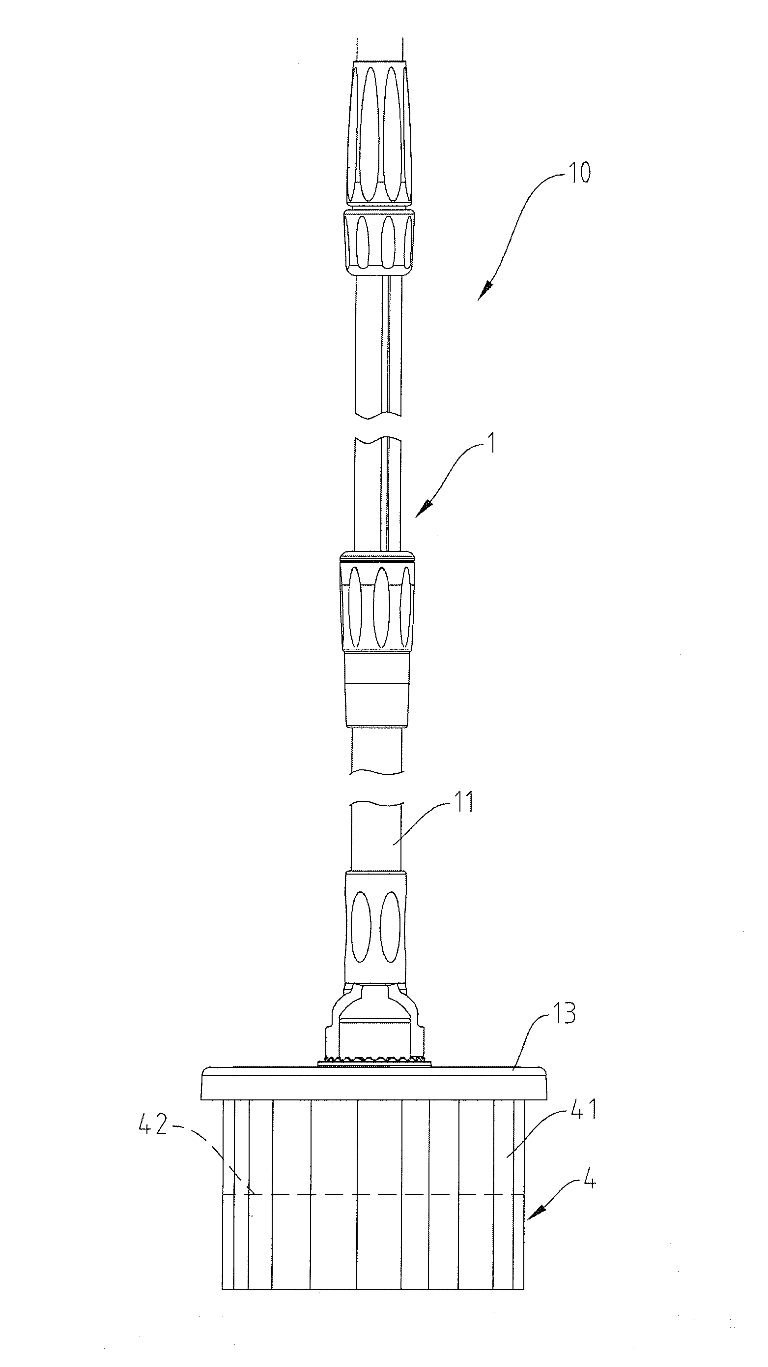
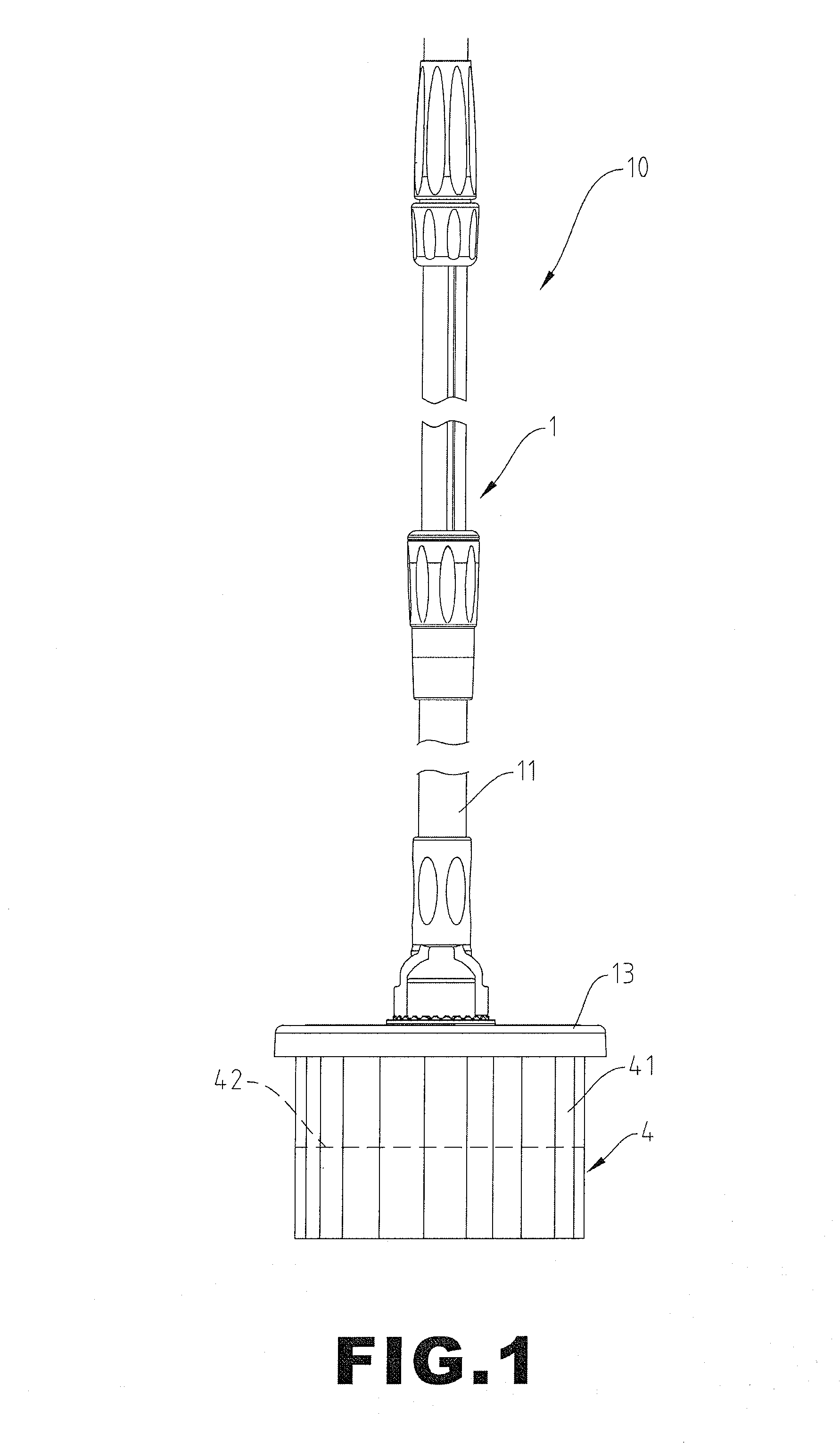
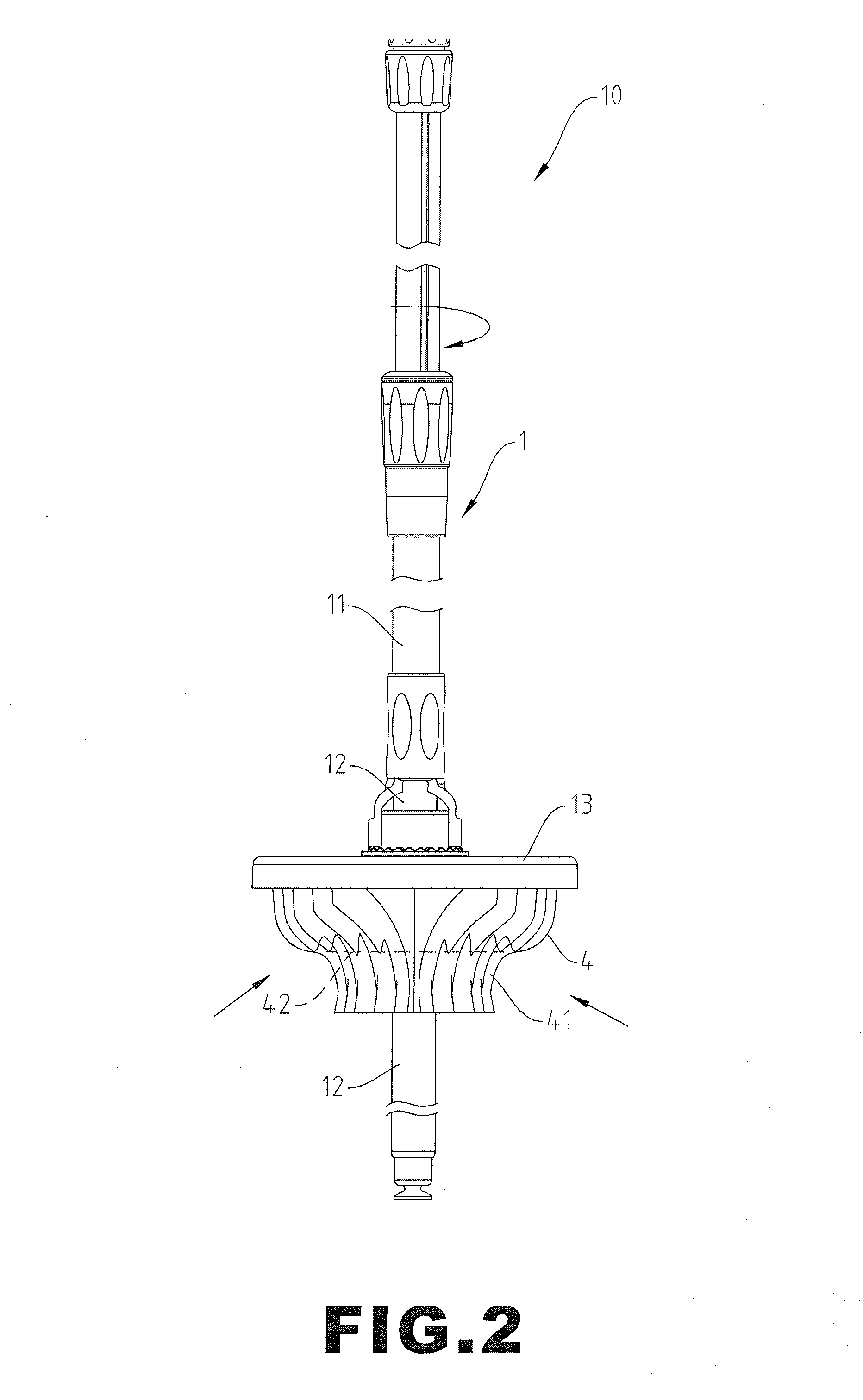
[0017]Referring to FIGS. 1-7, a swivel mop 10 in accordance with the preferred embodiment of the present invention comprises a handle unit 1, a first rotation disk 2, a second rotation disk 3, a cleaning unit 4, and a plurality of linking cords 5.

[0018]The handle unit 1 includes an outer tube 11, a connecting cap 13 mounted on a lower end of the outer tube 11, and an inner post 12 retractably and rotatably mounted in the outer tube 11 and extendable outward from the connecting cap 13. The inner post 12 of the handle unit 1 is driven by a first driving mechanism to rotate relative to the outer tube 11. The inner post 12 of the handle unit 1 has an outer periphery provided with a plurality of guiding tracks 121. The guiding tracks 121 of the inner post 12 are arranged in an annular manner and are equally spaced from each other. The connecting cap 13 of the handle unit 1 is driven by a second driving mechanism to rotate relative to the outer tube 11.

[0019]The first rotation disk 2 is c...


PUM

PropertyMeasurementUnit
centrifugal forceaaaaaaaaaa
sizeaaaaaaaaaa
lengthaaaaaaaaaa

Abstract

A swivel mop includes a handle unit, a first rotation disk, a second rotation disk, a cleaning unit, and a plurality of linking cords. The handle unit includes an outer tube, a connecting cap, and an inner post. The first rotation disk is connected with the connecting cap. The second rotation disk is driven by the inner post. The cleaning unit includes a plurality of cloth strips connected with the first rotation disk. The linking cords are connected between the second rotation disk and the cloth strips. Thus, when the second rotation disk is rotated by the inner post, the linking cords are driven by the second rotation disk to drive the cloth strips so that the cloth strips are driven toward a central portion to shorten the extent of expansion of the cloth strips during the dehydration process.

Description

BACKGROUND OF THE INVENTION [0001]1. Field of the Invention[0002]The present invention relates to a swivel mop and, more particularly, to a swivel mop with revolving dehydration function.[0003]2. Description of the Related Art[0004]A conventional swivel mop comprises a barrel and a mop body mounted in the barrel. The barrel has an interior provided with a basket which is pivotally mounted in the barrel. The mop body includes a retractable handle unit, a mop head connected with the handle unit, a plurality of cloth strips mounted on the mop head, and a rotation mechanism mounted in the handle unit and connected with the mop head. When a user wishes to dehydrate the cloth strips, the mop head is placed in the basket of the barrel so that the cloth strips are gathered in the basket. Then, the handle unit is retracted to drive the rotation mechanism which drives the mop head to swivel relative to the handle unit rapidly so as to rotate and dehydrate the cloth strips by a centrifugal for...

Claims


Application Information

Patent Timeline
Patent Type & Authority Patents(United States)
IPC IPC(8): A47L13/20
CPCA47L13/20A47L13/142A47L13/255
Inventor SHIH, CHIN-YANG
Owner SHIH CHIN YANG
Why Eureka
Try Eureka