
Method of manufacturing light emitting device

a technology of light-emitting devices and manufacturing methods, which is applied in the direction of semiconductor devices, basic electric elements, electrical appliances, etc., can solve the problems of color uniformity difficulties, uneven height of wavelength conversion parts formed on the surface of leds, and inability to meet the requirements for the distribution of wavelength conversion parts

Inactive Publication Date: 2015-01-06
SAMSUNG ELECTRONICS CO LTD
View PDF14 Cites 3 Cited by
  • Summary
  • Abstract
  • Description
  • Claims
  • Application Information

AI Technical Summary

Benefits of technology

[0010]An aspect of the present invention provides a method of manufacturing light emitting devices satisfying the requirements for the distribution of the height of a wavelength conversion part by allowing for uniformity in terms of the height of the wavelength conversion part when manufactured on a mass production basis.

Problems solved by technology

However, such a method of producing white light may require the use of a plurality of LEDs, and difficulties in color uniformity may occur.
However, such a method of mixing the phosphor material with the resin and applying the mixture thereof to the LED has a problem in that the height of a wavelength conversion part formed on a surface of the LED may be uneven.
In particular, in the case of LEDs manufactured on a mass production basis, requirements for the distribution of the height of the wavelength conversion part may not be satisfied.

Method used


Image

  • Method of manufacturing light emitting device
  • Method of manufacturing light emitting device
  • Method of manufacturing light emitting device

Examples


Embodiment Construction

[0038]Embodiments of the present invention will now be described in detail with reference to the accompanying drawings.

[0039]The invention may, however, be embodied in many different forms and should not be construed as being limited to the embodiments set forth herein. Rather, these embodiments are provided so that this disclosure will be thorough and complete, and will fully convey the scope of the invention to those skilled in the art.

[0040]In the drawings, the shapes and dimensions of elements may be exaggerated for clarity, and the same reference numerals will be used throughout to designate the same or like elements.

[0041]With reference to FIGS. 1 through 11, a method of manufacturing a light emitting device according to an embodiment of the invention will be described below.

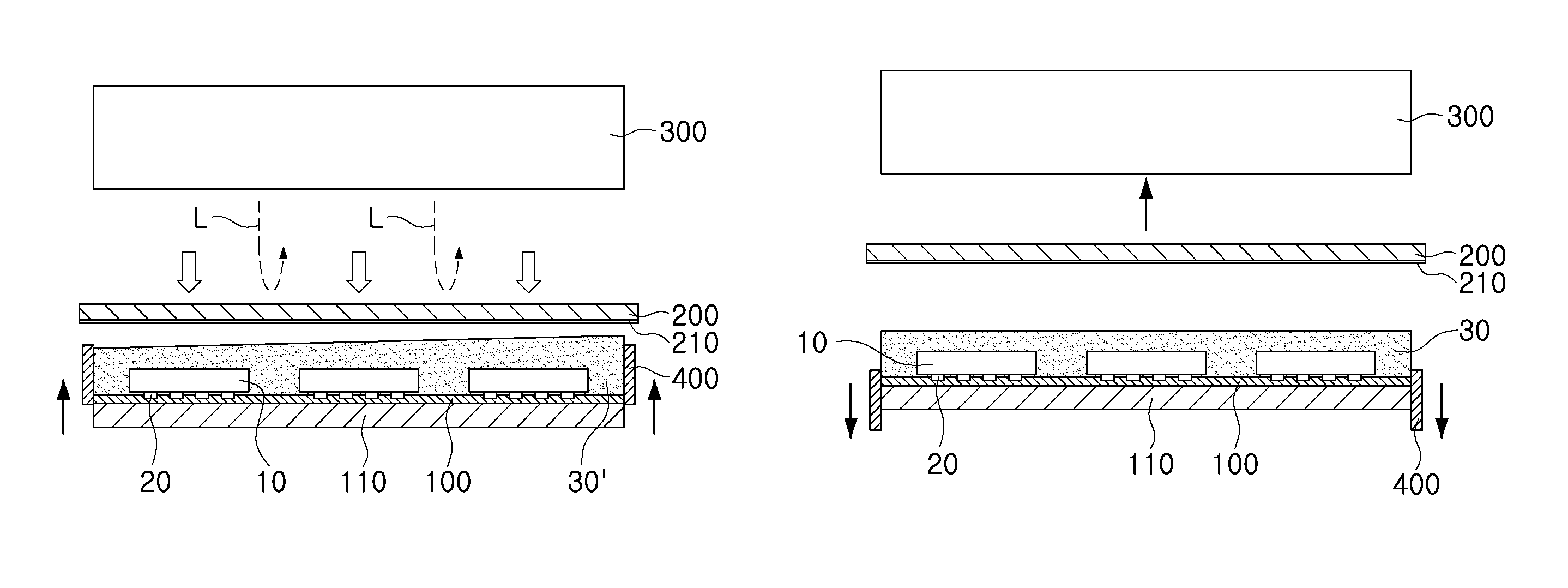
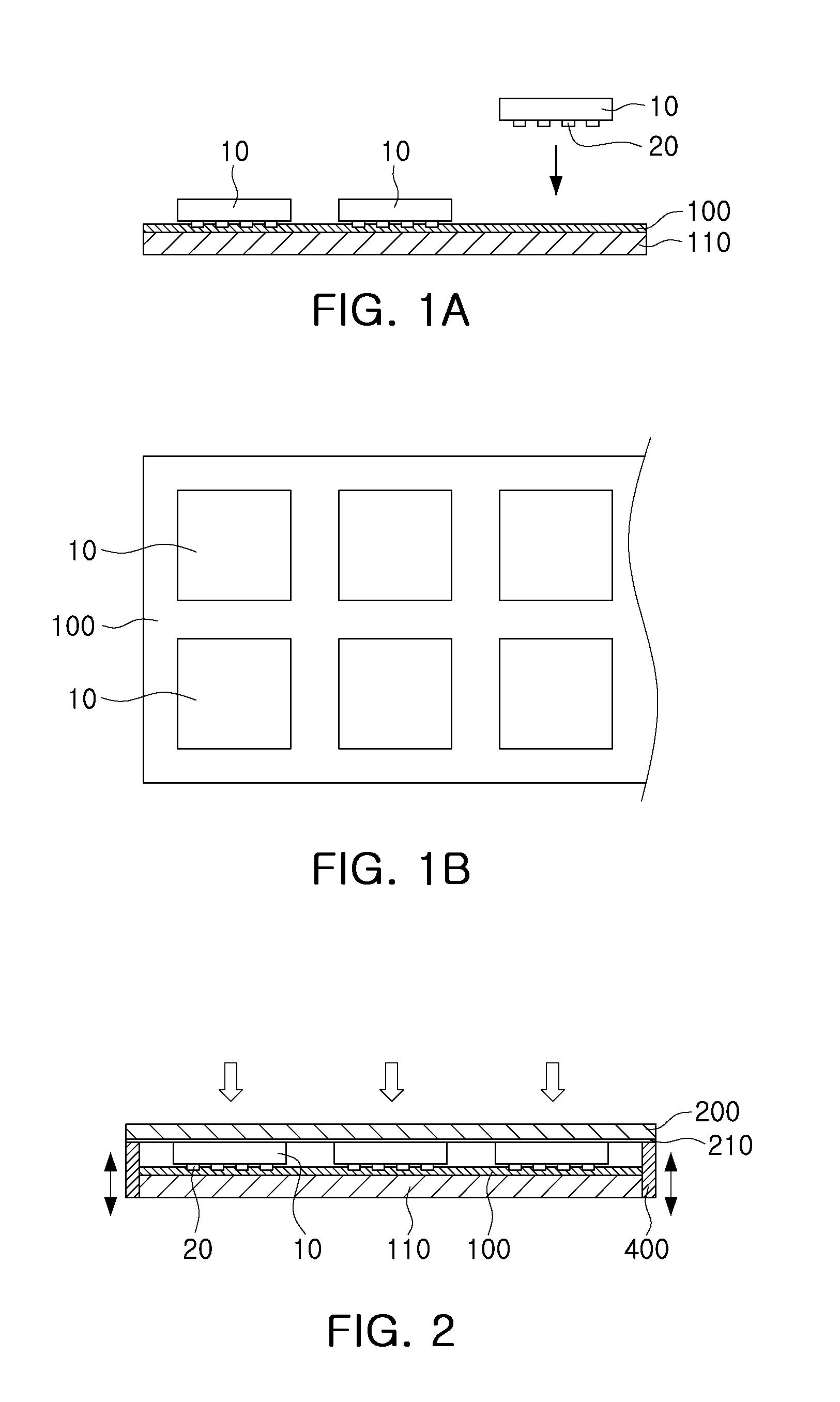
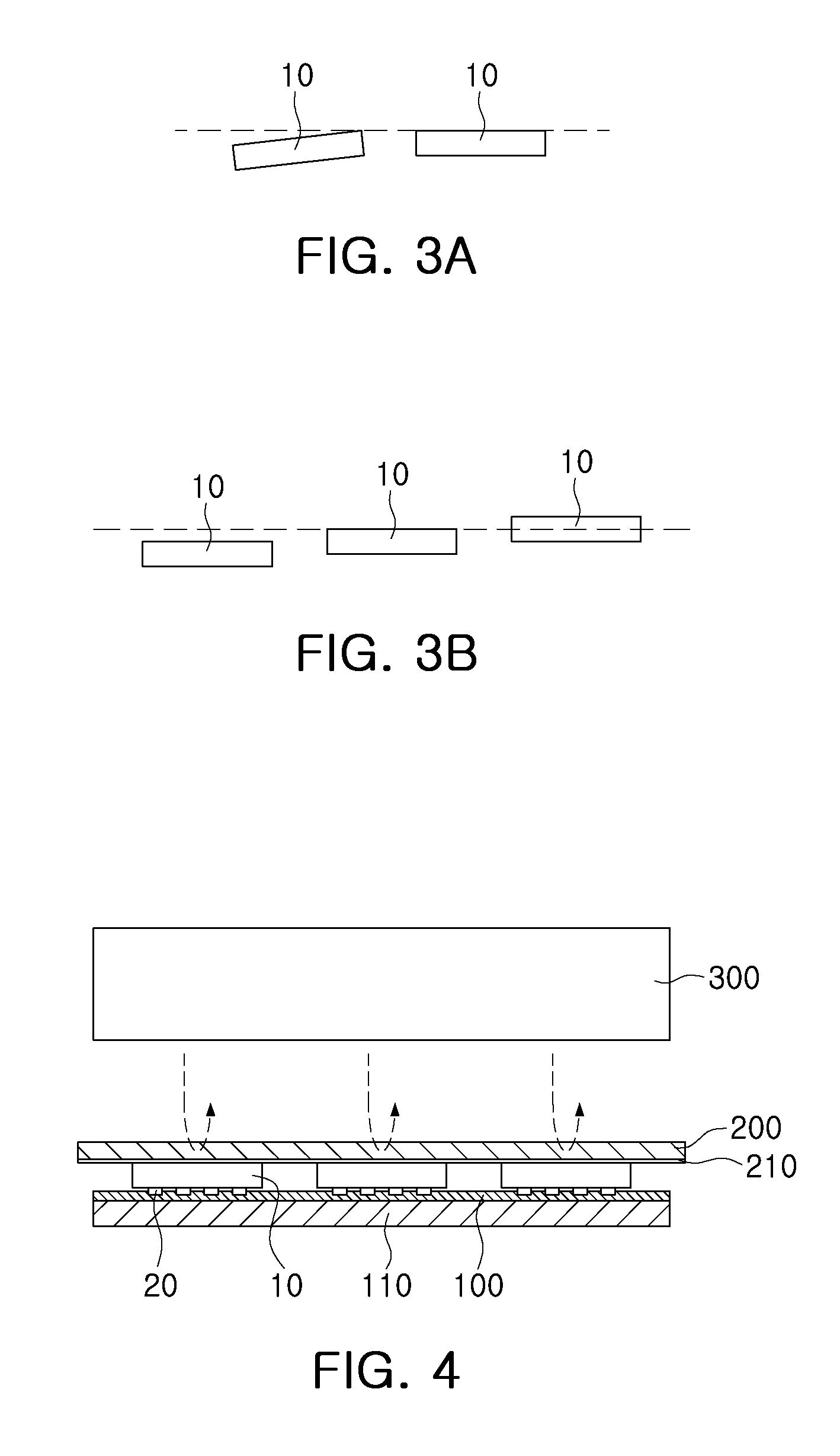
[0042]FIGS. 1A and 1B are schematic views illustrating mounting a plurality of light emitting devices on an adhesive layer according to an embodiment of the present invention. FIG. 2 is a schematic view il...


PUM


Abstract

There is provided a method of manufacturing a light emitting device, the method including: mounting a plurality of light emitting devices on an adhesive layer; arranging upper surfaces of the plurality of light emitting devices to be disposed horizontally using a pressing member; forming a wavelength conversion part covering the plurality of light emitting devices on the adhesive layer by applying a resin including at least one phosphor material; planarizing an upper surface of the wavelength conversion part using the pressing member; and separating the adhesive layer from the plurality of light emitting devices.

Description

CROSS-REFERENCE TO RELATED APPLICATIONS[0001]This application claims the priority of Korean Patent Application No. 10-2011-0075141 filed on Jul. 28, 2011, in the Korean Intellectual Property Office, the disclosure of which is incorporated herein by reference.BACKGROUND OF THE INVENTION[0002]1. Field of the Invention[0003]The present invention relates to a method of manufacturing a light emitting device.[0004]2. Description of the Related Art[0005]In recent years, a light emitting diode (LED), emitting light according to electrical signals, has been widely used as a light source for various types of electronic products, as well as mobile communication terminals such as personal cellular phones, personal digital assistants (PDAs), or the like.[0006]Such an LED is a light emitting device capable of emitting light of various colors by using compound semiconductor materials such as gallium arsenide (GaAs), aluminium gallium arsenide (AlGaAs), gallium nitride (GaN), indium gallium phosphi...

Claims


Application Information

Patent Timeline
Patent Type & Authority Patents(United States)
IPC IPC(8): H01L21/00H01L33/50H01L33/52
CPCH01L33/52H01L33/505H01L2933/0041H01L2933/005H01L2933/0091H01L33/50
Inventor SONG, JONG SUPYOU, JAE SUNGKIM, TAE GYU
Owner SAMSUNG ELECTRONICS CO LTD
Learn More