Separator plate with intermediate injection of gas, fuel cell, method of feeding a fuel cell

a technology of fuel cell and separation plate, which is applied in the direction of fuel cell details, fuel cell, electrochemical generator, etc., can solve the problems of water production and likely to diminish the performance of the fuel cell, and disrupt the supply

Active Publication Date: 2017-01-10
AREVA STOCKAGE DENERGIE
View PDF5 Cites 0 Cited by
  • Summary
  • Abstract
  • Description
  • Claims
  • Application Information

AI Technical Summary

Benefits of technology

[0008]One object of the invention is therefore to provide a separator plate that offers the ability to ensure a satisfactory distribution of reactant gas over a membrane electrode assembly.

Problems solved by technology

Therefore the operation of the fuel cell results in the production of water that is likely to disrupt the flow of the reactant gas in the grooves, in particular by creating clogging.
The disrupted supply is likely to diminish the performance of the fuel cell.

Method used


Image

  • Separator plate with intermediate injection of gas, fuel cell, method of feeding a fuel cell
  • Separator plate with intermediate injection of gas, fuel cell, method of feeding a fuel cell
  • Separator plate with intermediate injection of gas, fuel cell, method of feeding a fuel cell

Examples


Embodiment Construction

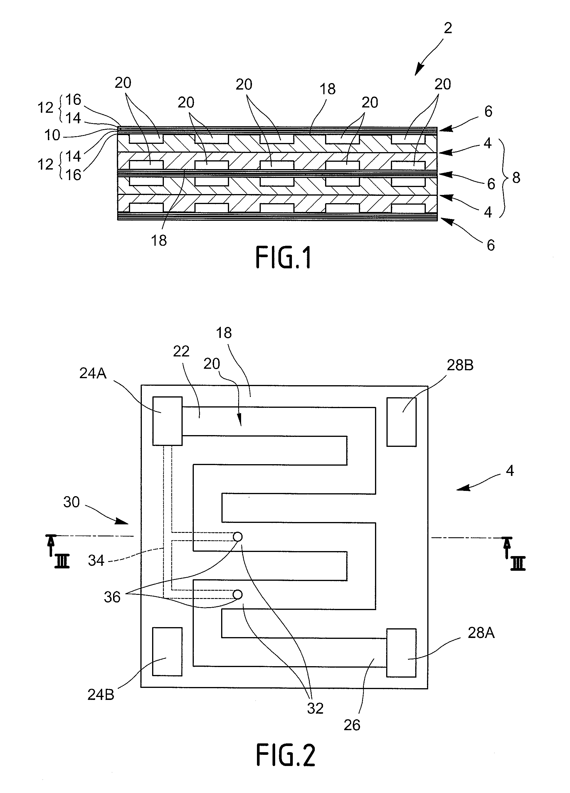
[0025]With reference to FIG. 1, the fuel cell 2 comprises a stack of separator plates 4 and membrane electrode assemblies 6 arranged in alternation. The universally accepted term “stack” is commonly used to refer to a stack as such.

[0026]Each membrane electrode assembly 6 is sandwiched between two separator plates 4. Each assembly formed of two separator plates 4 disposed on both sides of a membrane electrode assembly 6 defines an elementary electrochemical cell 8 of the fuel cell 2.

[0027]Each membrane electrode assembly 6 is in the form of a plate and is laminated. Each membrane electrode assembly 6 comprises an ion exchange membrane 10 and two electrodes 12 disposed on both sides of the membrane 10.

[0028]The membrane 10 is in particular a proton exchange membrane, and the fuel cell PEM type (“Proton Exchange Membrane”).

[0029]Each electrode 12 is electrically conductive. Each electrode 12 includes an active layer 14 and a gas diffusion layer 16. One electrode 12 defines an anode an...


PUM

PropertyMeasurementUnit
thicknessaaaaaaaaaa
electrical conductionaaaaaaaaaa
electrically conductiveaaaaaaaaaa

Abstract

A fuel cell separator plate is provided. The fuel cell separator plate includes at least one groove formed in a face of the separator plate so as to feed reactant gas to a membrane electrode assembly applied against the face of the separator plate, the groove comprising an inlet section and an outlet section. The fuel cell separator plate also includes injection means configured so as to inject gas into at least one intermediate section of the groove, situated between the inlet section and the outlet section.

Description

[0001]The present invention relates to the field of ion exchange membrane fuel cell.BACKGROUND[0002]An ion exchange membrane fuel cell comprises a stack of elementary electrochemical cells. Each electrochemical cell comprises a membrane electrode assembly (“MEA”) sandwiched between two separator plates.[0003]The membrane electrode assembly is laminated and comprises an ion exchange membrane sandwiched between two electrodes. Each electrode comprises an active layer adjacent to the membrane and a gas diffusion layer. One electrode makes up the anode and the other makes up the cathode.[0004]Each separator plate comprises grooves provided in its face which is pressed tight against the membrane electrode assembly in a manner so as to define between the separator plate and the membrane electrode assembly conduits for the circulation of a reactant gas in contact with the membrane electrode assembly.[0005]During operation of the fuel cell, fuel feeds the grooves of the anode side plate and...

Claims


Application Information

Patent Timeline
Patent Type & Authority Patents(United States)
IPC IPC(8): H01M8/02H01M8/04H01M8/10H01M8/12
CPCH01M8/026H01M8/0258H01M8/0267H01M8/04156H01M8/04007H01M2008/1095H01M2008/1293Y02E60/50Y02E60/525H01M8/0263H01M8/2483
Inventor QUINTIERI, CHRISTIAN
Owner AREVA STOCKAGE DENERGIE
Why Eureka
Try Eureka