
Fiber organizer and distribution box

a fiber and organizer technology, applied in the field of fiber organizers and boxes, can solve the problems of difficult connection of existing mdus to the fttx network, and achieve the effect of reducing axial strain

Active Publication Date: 2015-01-06
CORNING RES & DEV CORP
View PDF13 Cites 32 Cited by
  • Summary
  • Abstract
  • Description
  • Claims
  • Application Information

AI Technical Summary

Benefits of technology

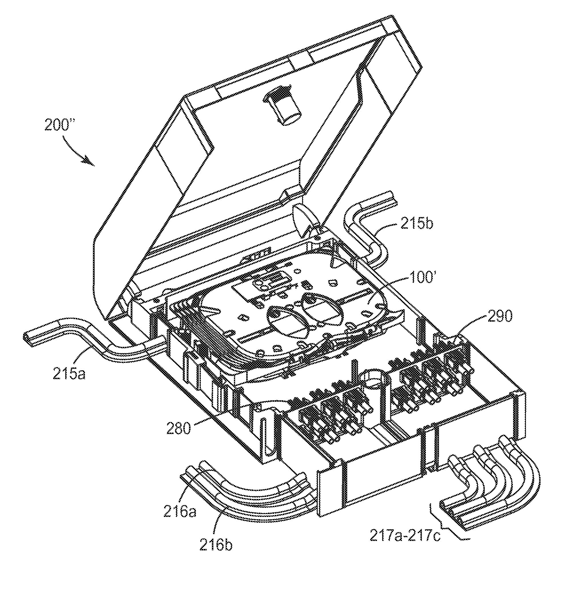
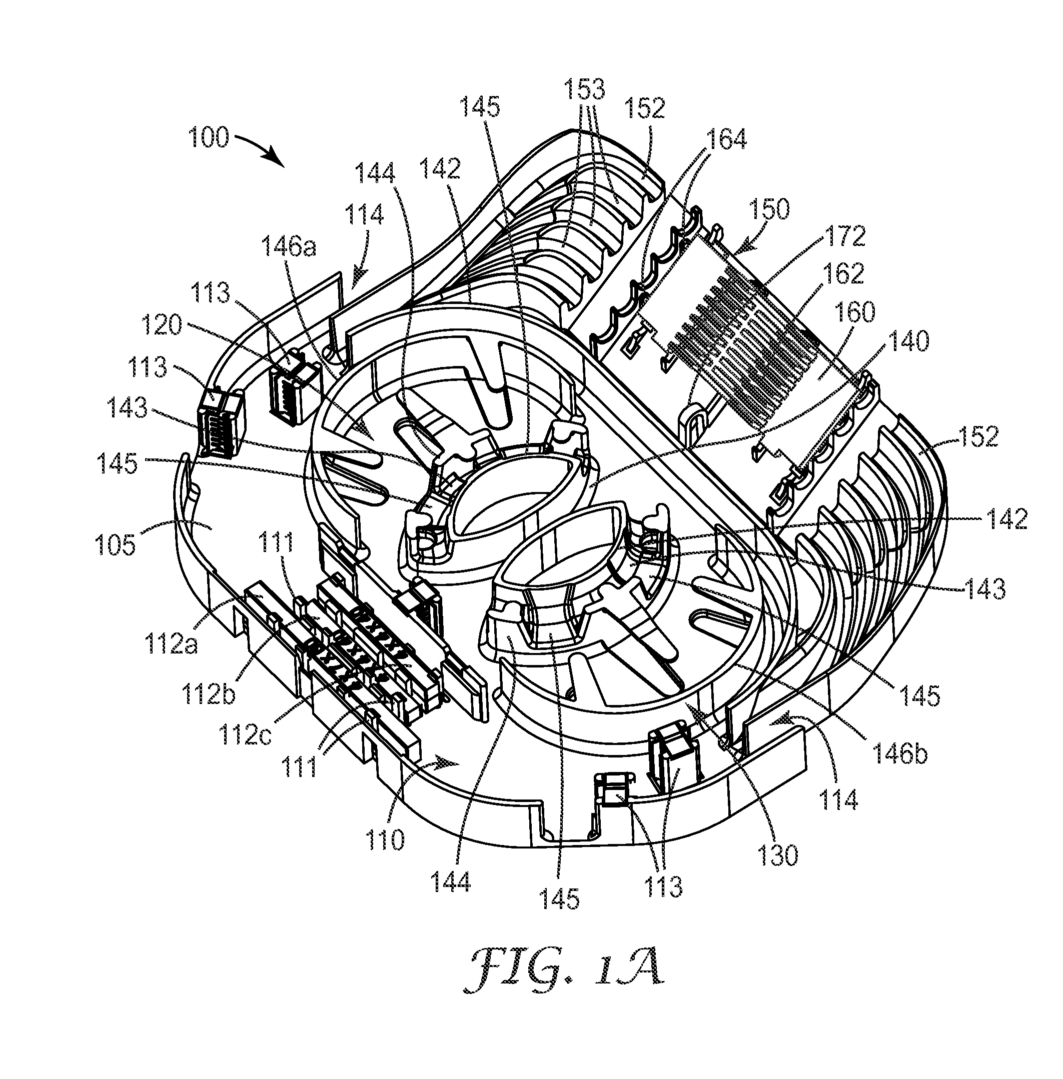
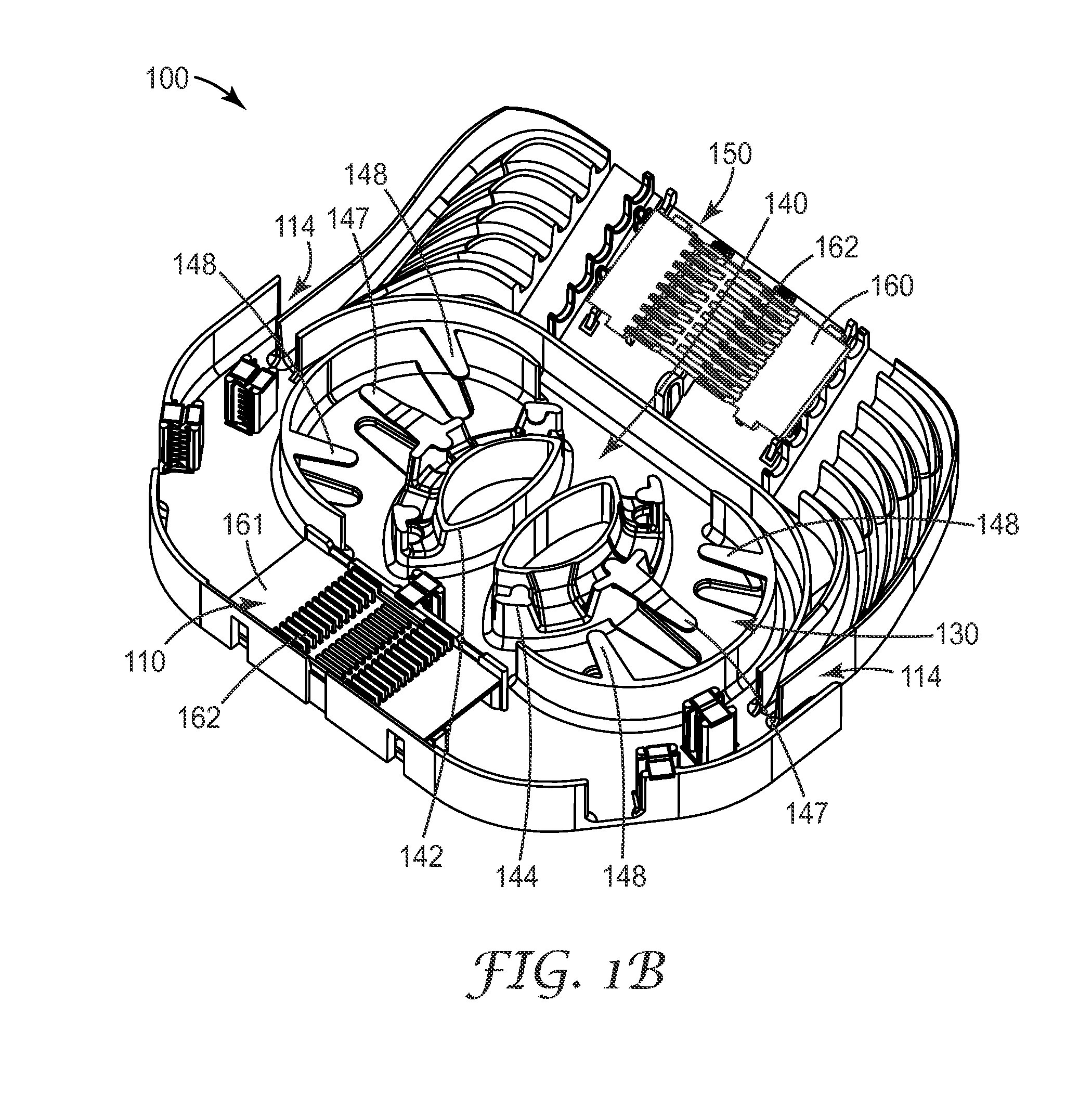
This patent describes a device that helps organize and manage fiber optic cables. It includes a half ring structure that allows for bending of the fiber at a proper angle, as well as overhanging tabs to keep the fiber in place. The device also has a splicing section that holds fiber cables, as well as a fiber ramp that delivers fibers and cables. Additionally, there are fiber channels that prevent individual fibers from crossing over into other channels. Overall, this device helps streamline the process of organizing and managing fiber optic cables.

Problems solved by technology

Connecting existing MDUs to the FTTX network can often be difficult.
Another challenge includes providing for multiple service providers.

Method used


Image

  • Fiber organizer and distribution box
  • Fiber organizer and distribution box
  • Fiber organizer and distribution box

Examples


Embodiment Construction

[0055]In the following Detailed Description, reference is made to the accompanying drawings, which form a part hereof, and in which is shown by way of illustration specific embodiments in which the invention may be practiced. In this regard, directional terminology, such as “top,”“bottom,”“front,”“back,”“leading,”“forward,”“trailing,” etc., is used with reference to the orientation of the Figure(s) being described. Because components of embodiments of the present invention can be positioned in a number of different orientations, the directional terminology is used for purposes of illustration and is in no way limiting. It is to be understood that other embodiments may be utilized and structural or logical changes may be made without departing from the scope of the present invention. The following detailed description, therefore, is not to be taken in a limiting sense, and the scope of the present invention is defined by the appended claims.

[0056]The present invention is directed to ...


PUM


Abstract

An organizer (100) for fiber cable management comprises a generally planar base (105) having a splitter holding section (110), a slack and unterminated fiber storage section (120), and a splice and splice tray holding section (150). The splitter holding section (110) is configured to optionally hold one or more fiber splitters. The slack and unterminated fiber storage section includes a slack storage region (130) having a plurality of fiber routing structures (146a, 146b) to support and retain slack fiber and an unterminated fiber storage region having one or more spool type structures (142) to support and retain unterminated fiber separate from the slack fiber. The splice and splice tray holding section is configured to optionally hold one of a first fiber splice insert (160) and a splice tray holder (170) configured to engage one or more splice trays. A distribution box (200) for distributing optical fibers for communications includes a base, a cover, and the organizer described above.

Description

THE FIELD OF THE INVENTION[0001]The present invention relates generally to a fiber organizer and box for distributing optical fibers for telecommunications.BACKGROUND OF THE INVENTION[0002]Telecommunication cables are used for distributing all manner of data across vast networks. A telecommunication cable typically includes a bundle of individual telecommunication lines (either optical fibers or copper wires) that are encased within a protective sheath. As telecommunication cables are routed across data networks, it is necessary to periodically open the cable so that one or more telecommunication lines therein may be spliced, thereby allowing data to be distributed to other cables or “branches” of the telecommunication network. The cable branches may be further distributed until the network reaches individual homes, businesses, offices, premises, and so on.[0003]At each point where a telecommunication cable is opened, some type of closure, box, or enclosure is provided to protect th...

Claims


Application Information

Patent Timeline
Patent Type & Authority Patents(United States)
IPC IPC(8): G02B6/00G02B6/44
CPCG02B6/4401G02B6/4441G02B6/445G02B6/4454G02B6/4477G02B6/44465G02B6/44528
Inventor PIMENTEL, NELSON GONCALVESGAERTNER, NORBERTFEHRENZ, MATTHIAS
Owner CORNING RES & DEV CORP
Learn More