
LDV for airdrops

a technology of airdrops and airdrops, applied in the field of airdrops, can solve the problems of significant degraded accuracy potential of precision drop, lack of wind data accuracy and timeliness required for precision drop,

Active Publication Date: 2015-01-06
RD2 LLC
View PDF13 Cites 4 Cited by
  • Summary
  • Abstract
  • Description
  • Claims
  • Application Information

AI Technical Summary

Benefits of technology

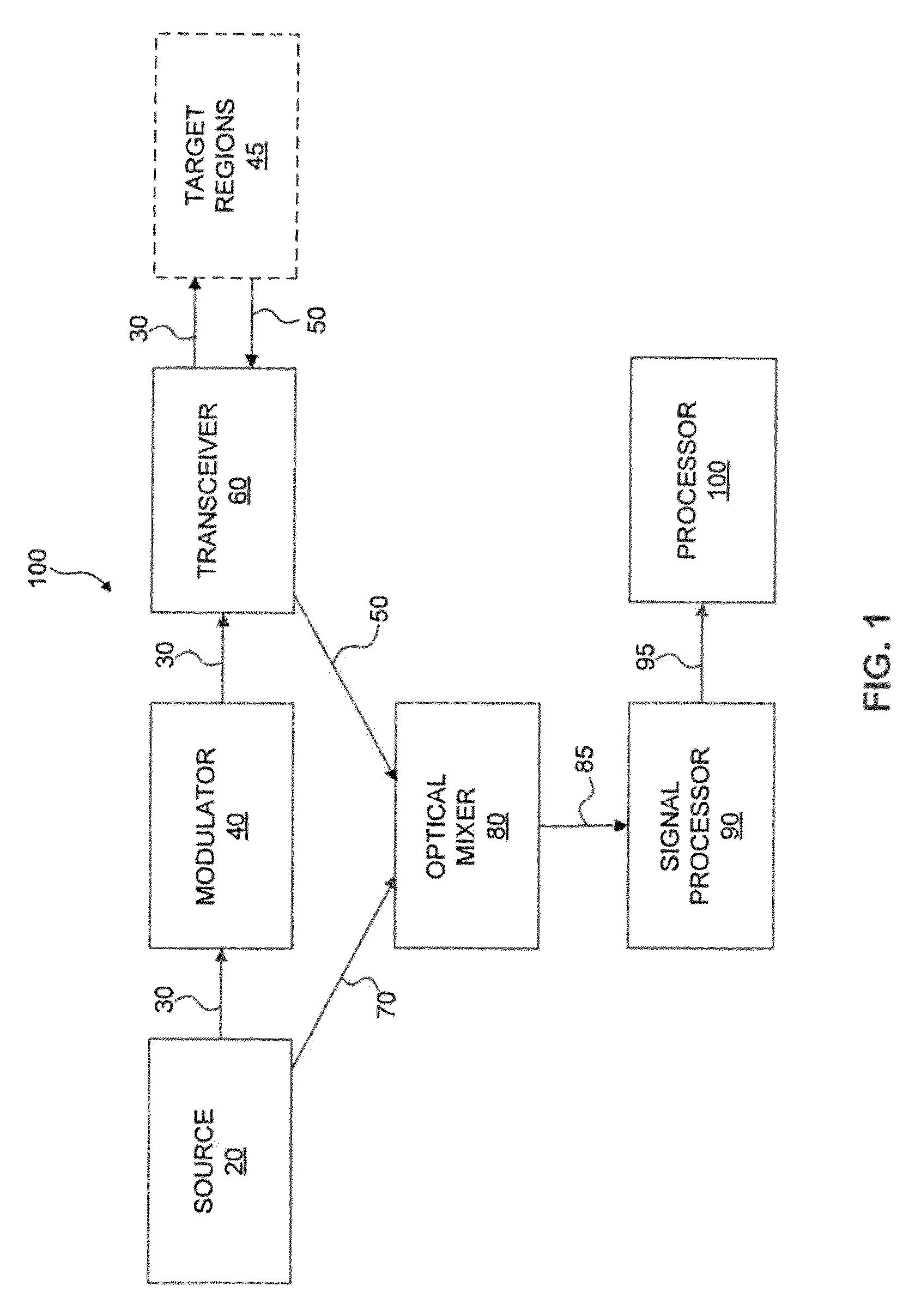
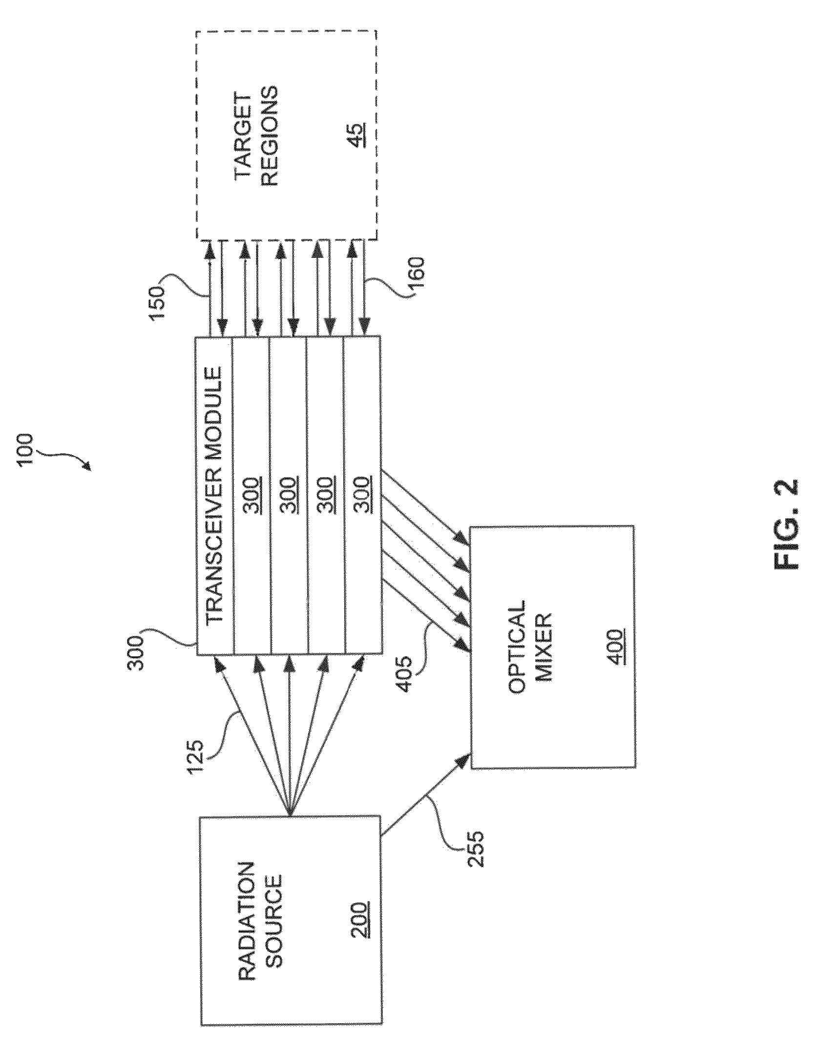
[0006]Therefore, what is needed is a compact, lightweight, and rugged aircraft mounted or ground based laser wind sensing system capable of reporting real time winds at multiple distances along a drop trajectory.
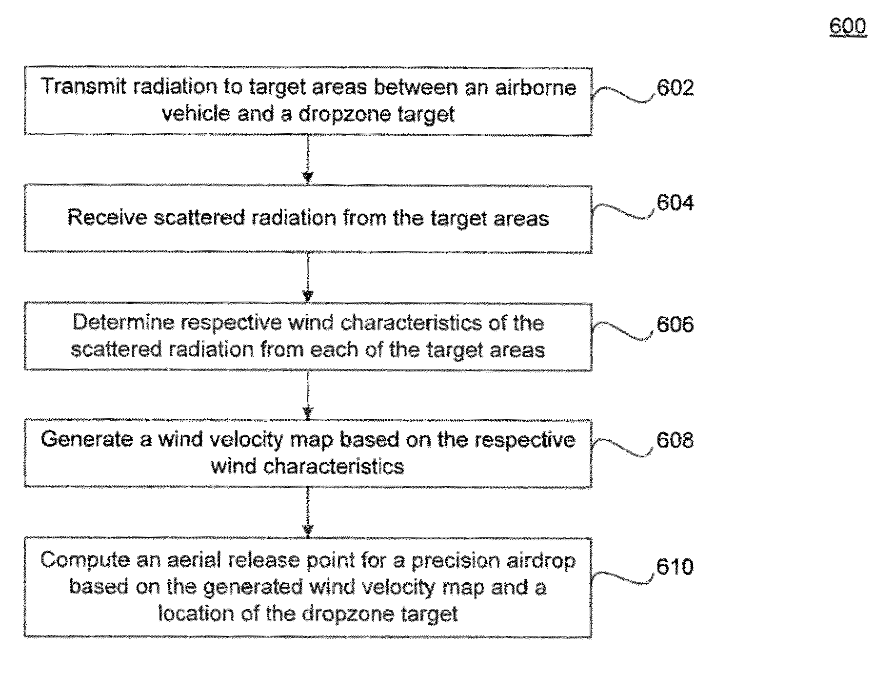
[0007]An embodiment of the present invention provides a method of using a light detection and ranging (LIDAR) system for increasing the accuracy of a precision airdrop. Radiation is transmitted to target areas between an airborne vehicle and a dropzone target. Scattered radiation is received from the target areas. Respective wind characteristics are determined from the scattered radiation and a wind velocity map is generated, based on the respective wind characteristics, between the airborne vehicle and at least the dropzone target. An aerial release point for the precision airdrop is computed based on the generated wind velocity map and a location of the dropzone target.
[0009]An embodiment of the present invention provides another method of using a light detection and ranging (LIDAR) system for increasing the accuracy of a precision airdrop. Radiation is transmitted to target areas above a dropzone target. Scattered radiation is received from the target areas. Respective wind characteristics are determined from the scattered radiation and a wind velocity map is generated, based on the respective wind characteristics, above the dropzone target. The wind velocity map is transmitted to one or more airborne vehicles.

Problems solved by technology

Such wind data lacks the accuracy and timeliness required for a precision drop.
Furthermore, since the final descent trajectory of the payload is ballistic, the accuracy potential for a precision drop is significantly degraded by the lack of any information regarding winds near the ground.

Method used


Image

  • LDV for airdrops
  • LDV for airdrops
  • LDV for airdrops

Examples


Embodiment Construction

[0019]This specification discloses one or more embodiments that incorporate the features of this invention. The disclosed embodiment(s) merely exemplify the invention. The scope of the invention is not limited to the disclosed embodiment(s). The invention is defined by the claims appended hereto.

[0020]The embodiment(s) described, and references in the specification to “one embodiment,”“an embodiment,”“an example embodiment,” etc., indicate that the embodiment(s) described may include a particular feature, structure, or characteristic, but every embodiment may not necessarily include the particular feature, structure, or characteristic. Moreover, such phrases are not necessarily referring to the same embodiment. Further, when a particular feature, structure, or characteristic is described in connection with an embodiment, it is understood that it is within the knowledge of one skilled in the art to effect such feature, structure, or characteristic in connection with other embodiments...


PUM


Abstract

A method of using a light detection system for increasing the accuracy of a precision airdrop is described. Radiation is transmitted to target areas between an airborne vehicle and a dropzone target. Scattered radiation is received from the target areas. Respective wind characteristics are determined from the scattered radiation and a wind velocity map is generated, based on the respective wind characteristics, between the airborne vehicle, and at least the dropzone target. An aerial release point for the precision airdrop is computed based on the generated wind velocity map and a location of the dropzone target.

Description

BACKGROUND[0001]1. Field of the Invention[0002]This disclosure relates to a system and a method to measure wind profiles around an airborne vehicle for improving the accuracy of precision airdrops.[0003]2. Background Art[0004]The knowledge of real-time winds is important for precision airdrop of cargo and consumables. Such airdrops are performed commonly to Forward Operating Bases as well as remote and dispersed austere locations. Recent technological advances have allowed precision airdrops to be performed at higher altitudes, taking the aircraft out of the reach of ground threats.[0005]Newer airdrop systems provide a variety of atmospheric sensing capabilities, except for the ability to measure real-time winds. The wind information is estimated from dropsonde data as well as pilot wind reports at the aircraft's altitude. Such wind data lacks the accuracy and timeliness required for a precision drop. Furthermore, since the final descent trajectory of the payload is ballistic, the a...

Claims


Application Information

Patent Timeline
Patent Type & Authority Patents(United States)
IPC IPC(8): G01S17/95B64C19/00G01S17/50G01S17/58G01S17/88G05D1/10
CPCB64C19/00G01S17/50G01S17/88G01S17/58G01S17/95G05D1/105Y02A90/10
Inventor MAMIDIPUDI, PRIYAVADANDAKIN, ELIZABETH A.DAKIN, DANIEL C.ROGERS, PHILIP L.DEDE, EDGAR K.GATCHELL, PETERPANABAKAM, MADHUKIRANLECLAIR, LANCECHANG, CHIA-CHENCHANGKAKOTI, RUPAK
Owner RD2 LLC
Learn More