Rail-less roof mounting system

Active Publication Date: 2015-01-27
WENCON DEV INC
View PDF147 Cites 111 Cited by
  • Summary
  • Abstract
  • Description
  • Claims
  • Application Information

AI Technical Summary

Benefits of technology

[0025]Yet still another object of the present invention is to provide a rail-less roof mounting system that eliminates the need to transport to the jobsite, configure and cut long heavy rails for installation purposes.
[0026]Still yet another object of the present invention is to provide a rail-less roof mounting s

Problems solved by technology

However, most of the mounting structures require increased labor time and cost for installation of the PV modules on the roof structures.
Conventional mounting structures for supporting PV modules in frames have considerable drawbacks.
Because of use of the additional material, these traditional mounting structures can result in excess shipping costs.
They can also limit the PV array layout possibilities and dramatically increase the time for designing, engineering and installing the mounting structures.
Existing devices are expensive, difficult to use and can require additional manpower to install.
In addition, existing rail mounting systems may have substandard waterproofing for roof penetrations, along with complex grounding, wire management, and increased labor time on the roof structure due to design flaws.
The hard and soft balance of system (BOS) costs for PV rail mounting system are high due to high material costs as well as long system engineering and installation times. Also, the traditional rail moun

Method used


Image

  • Rail-less roof mounting system
  • Rail-less roof mounting system
  • Rail-less roof mounting system

Examples


Example

DETAILED DESRIPTION OF THE DRAWINGS

[0042]In the following discussion that addresses a number of embodiments and applications of the present invention, reference is made to the accompanying drawings that form a part hereof, and in which is shown by way of illustration specific embodiments in which the invention may be practiced. It is to be understood that other embodiments may be utilized and changes may be made without departing from the scope of the present invention.

[0043]Various inventive features are described below that can each be used independently of one another or in combination with other features. However, any single inventive feature may not address any of the problems discussed above or only address one of the problems discussed above. Further, one or more of the problems discussed above may not be fully addressed by any of the features described below.

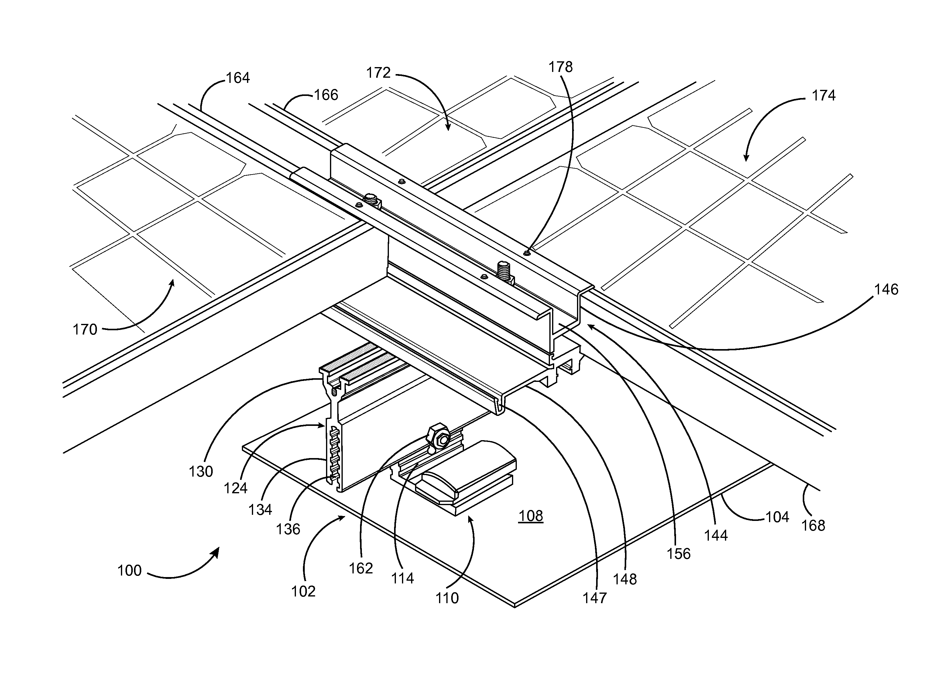
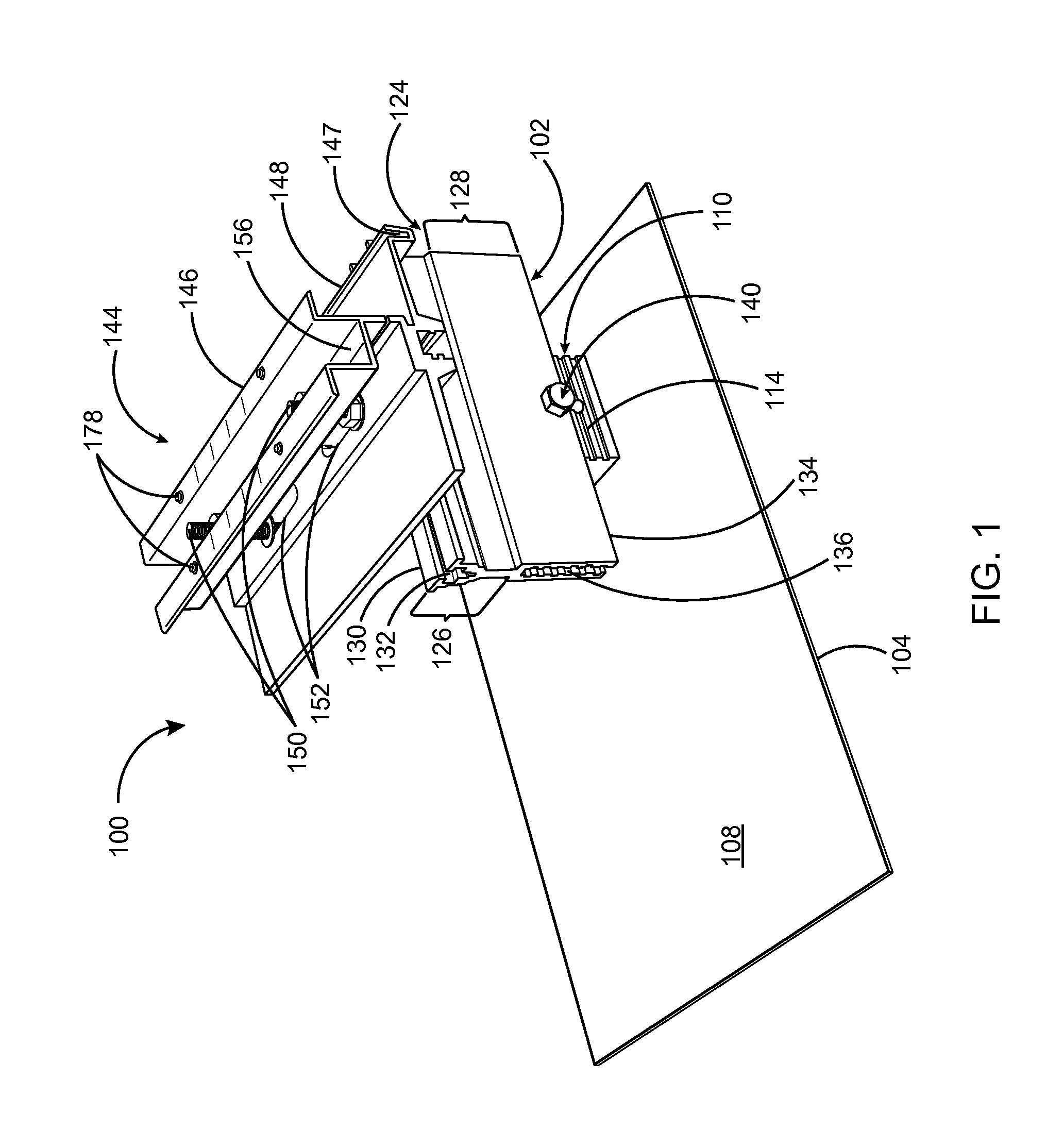
[0044]Turning now to FIG. 1, a perspective view of a rail-less roof mounting system 100 for installing a plurality of ...


PUM


Abstract

A rail-less roof mounting system for installing photovoltaic (PV) modules on a roof structure comprises a base mount assembly that engages with a clamp assembly and attaches to the roof structure. The base mount assembly comprises a base member having a waterproof means, a block slider, a top slider and a covering means. An elevated seal portion of a block slider includes a borehole to receive the waterproof means. A vertical engaging portion of the block slider is attached with a sliding seal member of the top slider. The clamp assembly includes a clamp member and a plate member and the clamp member is attached with a track of the top slider. The clamp member interlocks the PV modules to provide a corner-to-corner coupling arrangement, which enables the connection of PV module corners to adjacent PV module corners by sandwiching above and beneath frame members of the PV modules.

Description

RELATED APPLICATIONS[0001]This application claims priority from the U.S. provisional Application with Ser. No. 61 / 916046 filed on Dec. 13, 2013. The disclosure of the provisional application is incorporated herein as if set out in full.BACKGROUND OF THE DISCLOSURETechnical Field Of The Disclosure[0002]The present embodiment relates in general to mounting systems for photovoltaic (PV) modules on roof structures. More specifically, the present disclosure relates to a rail-less photovoltaic (PV) module mounting system for providing a cost-effective means to install a plurality of photovoltaic (PV) modules on a roof structure.DESCRIPTION OF THE RELATED ART[0003]With the increased use of photovoltaic (PV) roofing systems for generating electricity, a demand for mounting hardware, which attaches frames for the purpose of installing the PV modules to the roof structure or any other support structure, has been developed. In recent years, various kinds of mounting structures have been used w...

Claims


Application Information

Patent Timeline
IPC IPC(8): E04D13/18
CPCY02B10/20Y02E10/47F24S25/33F24S25/61F24S25/636F24S25/70F24S2025/6008F24S2025/803F24S2025/807H02S20/23Y02E10/50Y02B10/10
Inventor WENTWORTH, STUARTWENTWORTH, CLAUDIA
Owner WENCON DEV INC
Why Eureka
Try Eureka