Method and means for data management in a laboratory

a laboratory and data management technology, applied in the field of laboratory data management, can solve the problems of human error, reduced results, and increased risk of left over labels being erroneously applied to containers for a different patient, so as to improve the quality of the system and minimize management errors

Inactive Publication Date: 2004-12-21
DIESSE DIAGNOSTICA SENESE
View PDF12 Cites 11 Cited by
  • Summary
  • Abstract
  • Description
  • Claims
  • Application Information

AI Technical Summary

Benefits of technology

A first object of the present invention is to provide a method and a system for laboratory data management which makes it possible to minimize management errors and thus improve the quality of the system.
In an improved embodiment of the method according to the invention, however, the central computer can be programmed to receive from the individual analyzers the results of the analyses combined with the identification codes of the containers. In this case, the same central computer will receive, from the unit supplied to the operator in the specimen taking room, the combination of the patient code and the identification codes of the containers assigned to the individual patient, and will be programmed in such a way that the patient code is re-associated with the results of the analyses by means of the aforesaid combination. In this embodiment, the method permits simpler processing of the data, but requires the reprogramming of the data processing system and makes it necessary to carry out all analyses by the new method, in other words to have all the containers identified by corresponding identification codes.

Problems solved by technology

In spite of the efforts made by manufacturers of equipment and materials for diagnostic analysis, however, situations occur in the course of application in the analytical laboratory and / or in a hospital complex which give rise to errors and thus reduce the quality of the results obtained.
Even if there is maximum automation of the data management system in the analytical laboratory, errors due to various causes may occur and give rise to serious consequences in that the patients receive results relating to biological specimens of different patients.
A first set of errors originates from the system of labeling with patient codes.
A first and more evident error is the human error which consists in attaching a label bearing the bar code of a patient to the wrong container.
This error is commonly caused by the uncomfortable conditions in which the personnel have to work in the specimen-taking room.
Specimen-taking containers vary according to their manufacturers, and this gives rise to numerous problems, since the area for the application of the label to the container is not always compatible with the size of the label.
The use of a sheet carrying a plurality of self-adhesive labels, the number of which usually exceeds that of the containers which are actually to be used, is a source of waste, since for each patient several unused labels are frequently thrown away.
The presence of left over labels increases the risk that left over labels will be erroneously applied to containers for a different patient.
Moreover, the use of self-adhesive labels makes it necessary to print the whole patient sheet on self-adhesive material which is expensive.
The operation of detaching and applying the adhesive labels is time-consuming and laborious and reduces the time available for personnel responsible for specimen taking, thus increasing the waiting time for specimen taking.
However, this significantly increases personnel costs, or diverts personnel from more important activities.
The overall quality of the result is ultimately affected by this.
There are also difficulties due to the lack of a uniform standard applied in the field.
The paradox lies in the fact that neither the manufacturers nor the software houses have a model which can act as a standard, and consequently, whenever a manufacturer's new data processing system is installed in a laboratory, considerable efforts are required to make the system compatible, and this also happens in each laboratory for all the new instruments that arrive.

Method used


Image

  • Method and means for data management in a laboratory
  • Method and means for data management in a laboratory
  • Method and means for data management in a laboratory

Examples


Embodiment Construction

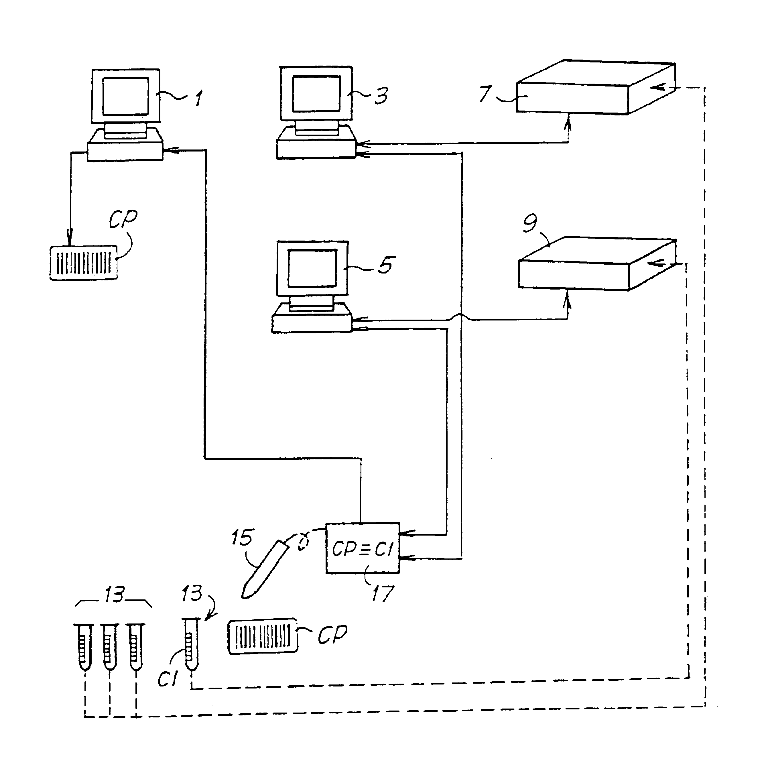
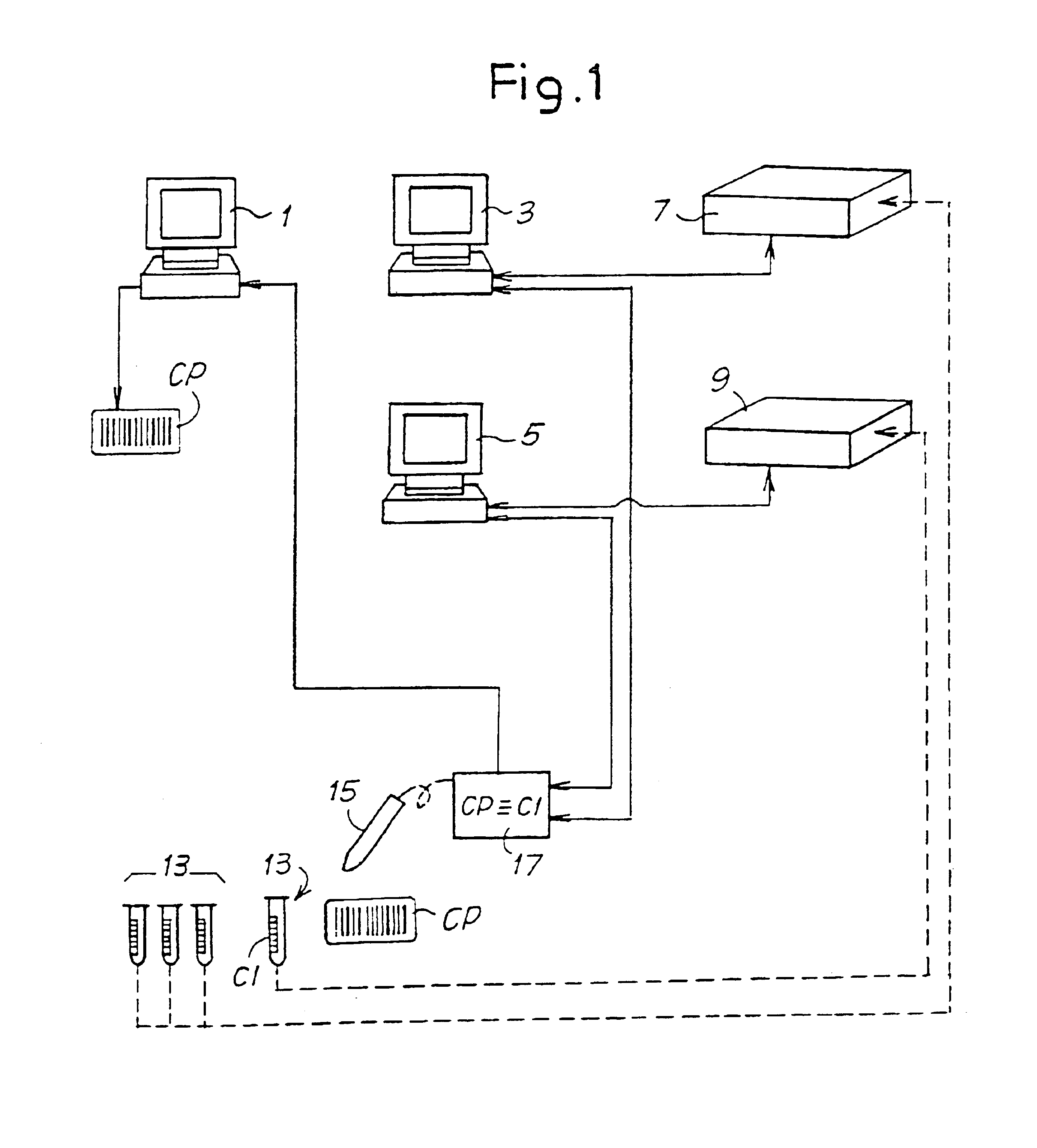
FIG. 1 shows schematically a network of units forming a data processing system in which the method according to the present invention can be implemented. The number 1 indicates a central electronic computer (host computer). The central computer 1 is programmed to acquire the patient data and to generate for each patient a patient code CP, which for example is printed in the form of a bar code on a paper medium.

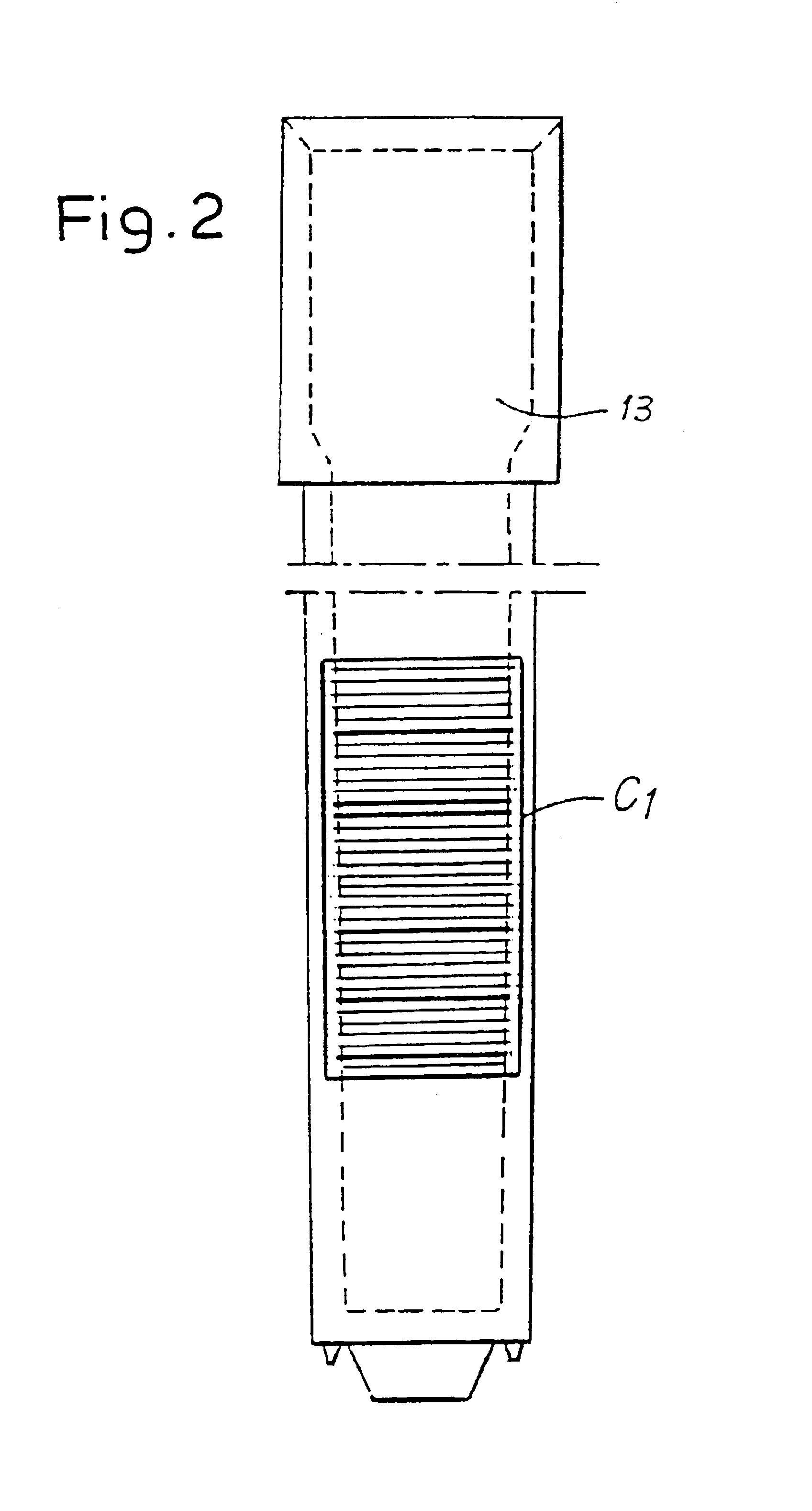
The numbers 3 and 5 indicate two peripheral electronic computers for monitoring and operating corresponding analyzers 7 and 9. The patient whose data have been acquired by the central computer 1 and for whom a patient code CP has been output passes into an area for taking biological specimens, showing his patient code CP, and here an operator takes the specimen and places, for example, the blood (or other biological specimen) in one or more containers 13. Each container 13 is provided with an identification code CI, which is unique and absolute, in other words different for ea...


PUM


Abstract

A method for data management in an analytical laboratory and a data management system include containers provided for the laboratory analysis of biological specimens. Each container is associated with its own identification code. A patient code is associated with a patient to be subjected to analysis. For each container used for a patient, a combination of a patient code and the identification code of the corresponding container is generated in a data processing system. At least one analyzer is used to carry out at least one analysis on the container or containers used for the patient. The analyzer enters the results of the analysis, combined with the identification code of the container or containers, into the data processing system.

Description

The present invention relates to a method for data management in an analytical laboratory, particularly in a laboratory for analyzing biological specimens from patients.The invention also relates to a system for data management in an analytical laboratory.Finally, the invention relates to a container for use in the method and with the system mentioned above.PRIOR ARTIn the era of total quality, high standards of safety and reliability are required in the diagnostic field as in other areas. In spite of the efforts made by manufacturers of equipment and materials for diagnostic analysis, however, situations occur in the course of application in the analytical laboratory and / or in a hospital complex which give rise to errors and thus reduce the quality of the results obtained.At the present time, containers of various types, particularly test tubes, cups, racks, microplates and others, are used for carrying out a multiplicity of analyses of the diagnostic type. In the present descripti...

Claims


Application Information

Patent Timeline
IPC IPC(8): G06F19/00G01N35/00G01N33/48G01N35/02G06Q50/00
CPCG06F19/366G06F19/322G16H10/60G16H10/40
Inventor COCOLA, ADRIANOMELONI, MICHELE
Owner DIESSE DIAGNOSTICA SENESE
Why Eureka
Try Eureka