Solar tracking bearing and solar tracking system employing same

a technology of solar tracking and bearings, applied in the direction of bearing unit rigid support, heat collector mounting/support, light and heating apparatus, etc., can solve the problems of safety concerns, high cost of bearing designs, and bottlenecks in construction equipmen

Active Publication Date: 2015-01-27
FIRST SOLAR INC (US)
View PDF20 Cites 38 Cited by
  • Summary
  • Abstract
  • Description
  • Claims
  • Application Information

AI Technical Summary

Problems solved by technology

Within solar trackers, bearing designs have traditionally been particularly high in cost due to material usage, required part counts, and complexity of manufacturing.
In addition, assembly of such bearings generally requires field welding or beam-to-beam bolting.
This requires the presence of skilled workers in remote locations, causes safety concerns, and creates bottlenecks around construction equipment.

Method used


Image

  • Solar tracking bearing and solar tracking system employing same
  • Solar tracking bearing and solar tracking system employing same
  • Solar tracking bearing and solar tracking system employing same

Examples


first embodiment

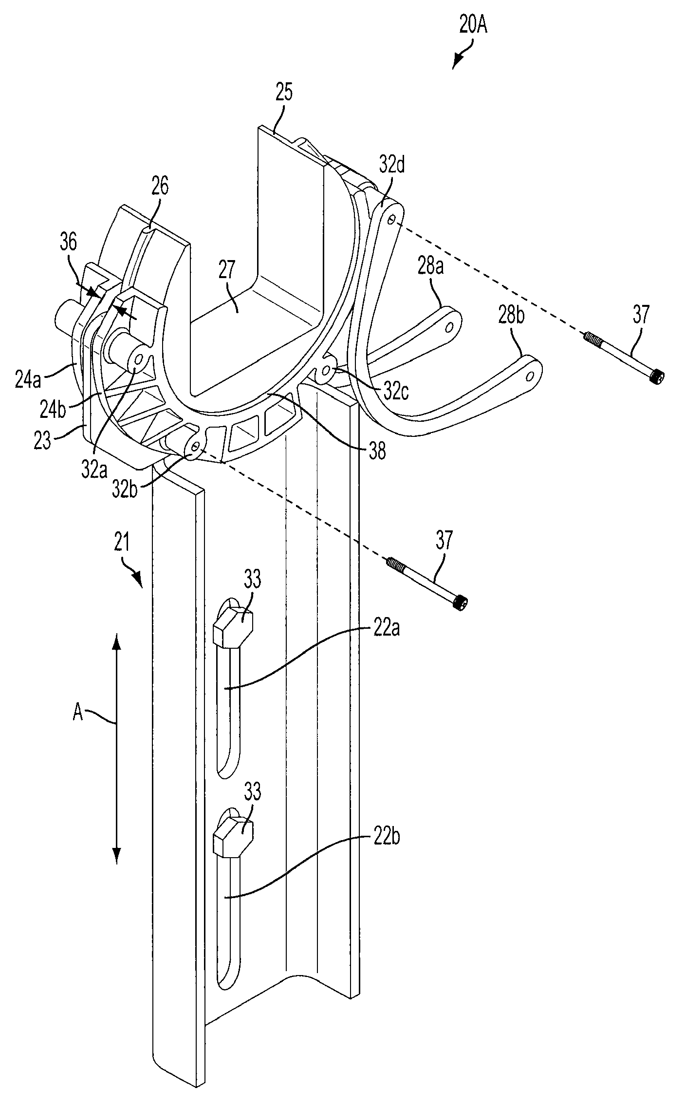
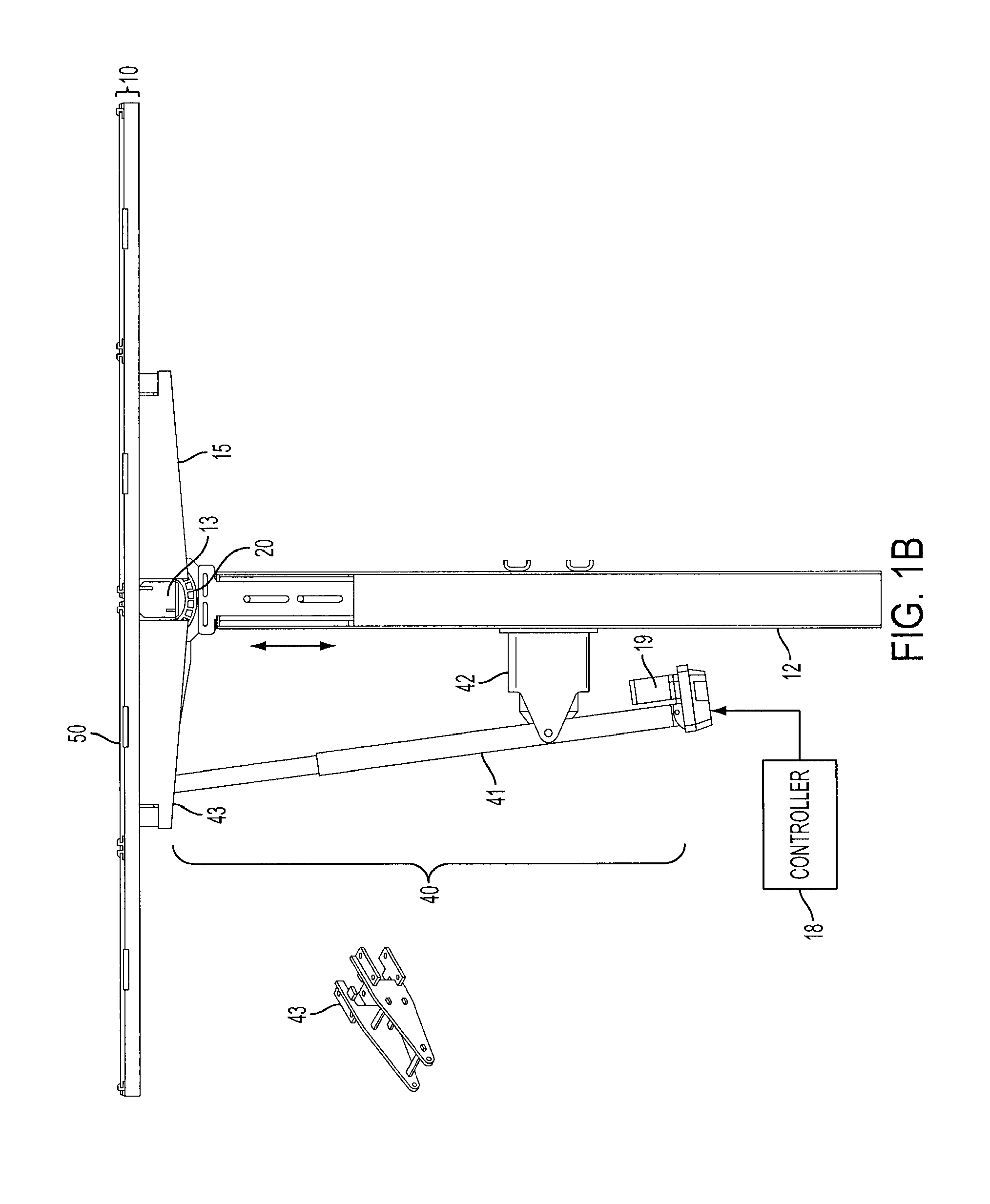
[0019]FIGS. 2A and 2B show a solar tracker bearing, 20A. Bearing 20A comprises a bearing securing element 21 which mounts bearing 20A to a support post 12 (as better shown in FIG. 1B). Bearing securing element 21 comprises a pair of Z-axis (height) adjustable mounting slots 22a and 22b, through which bolts, screws, or other attachment means 33 may pass to mount bearing securing element 21 to support post 12. In this manner, the Z-axis position (height) of the entire bearing 20A can be easily adjusted along the direction of arrow A.

[0020]Atop bearing securing element 21 is a rigid U-shaped bearing support element 23 to which a pair of stationary U-shaped outer bearing races 24a and 24b are mounted, one on either side, through one or more mounting holes 32a-d extending through outer bearing races 24a and 24b and bearing support element 23, by bolts, screws or other attachment means 37. The mounting holes may be arranged so that the mounting of each outer bearing race 24a and 24b emplo...

second embodiment

[0028]FIGS. 3A and 3B show a solar tracker bearing, 20B, which separates the bearing securing element 21 from U-shaped bearing support element 23. In bearing 20B, bearing support element 23 is mountable to bearing securing element 21 at a pair of transversely adjustable mounting slots 30a and 30b on an upper flange 29 of bearing securing element 21. Bolts, screws, or other attachment means 34 may pass through the slots 30a, 30b and into or through holes in bearing support element 23 to secure bearing support element 23 to bearing securing element 21. This embodiment permits the transverse position of bearing 20B to be adjusted relative to support post 12 in the direction of arrow B.

third embodiment

[0029]FIG. 6 shows a solar tracker bearing, 20C, which omits inner bearing race 25 and mounts a round torque tube 13C directly on surface 38 in a single outer bearing race 24C.

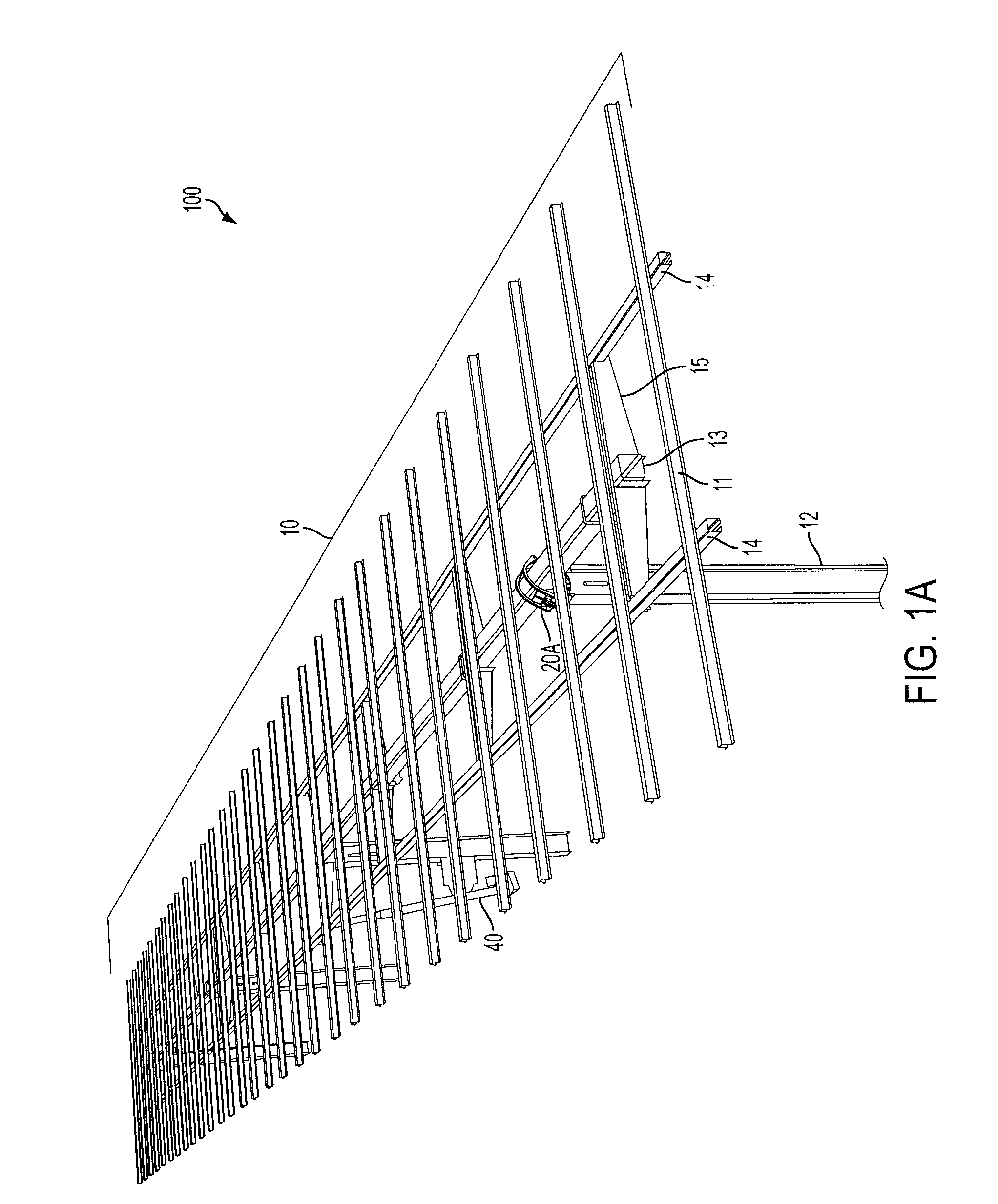
[0030]The bearing designs 20A, 20B and 20C shown in FIGS. 2A-2B, 3A-3B and 6 are all suitable for mass production and easy installation, as they have relatively few parts and allow a simple design for rotation of torque tube beams 13. This lowers the total cost of a solar tracker system 100 using bearings 20A, 20B or 20C, and reduces installation crew size.


PUM


Abstract

An solar tracker bearing comprising a pair of stationary outer bearing races attached on either side of a bearing support element and a rotatable inner bearing race held by the pair of outer bearing races, the rotatable inner bearing race having an beam slot for seating a torque tube beam therein.

Description

CROSS-REFERENCE[0001]This application claims priority to Provisional U.S. Patent Application No. 61 / 522,734, filed on Aug. 12, 2011, the disclosure of which is incorporated by reference in its entirety.FIELD OF THE INVENTION[0002]Embodiments of the invention relate generally to photovoltaic systems, and more specifically to solar tracking systems.BACKGROUND OF THE INVENTION[0003]Photovoltaic power generation systems convert solar radiation to electrical current using photovoltaic modules. To provide increased (and more consistent) energy generation over the course of a day, power generation systems can employ solar trackers that change the inclination of the photovoltaic modules to maintain a fixed angle of incidence between the Sun and the photovoltaic modules.[0004]Generally, solar trackers require very high mechanical system reliability and low part and installation costs to enable deployment in utility scale photovoltaic power generation systems. Within solar trackers, bearing d...

Claims


Application Information

Patent Timeline
Patent Type & Authority Patents(United States)
IPC IPC(8): F16C35/00F24J2/54
CPCF24J2/541F24J2002/5451F24J2002/5468F24J2002/5482Y02E10/47F24S25/12F24S25/65F24S25/70F24S30/425F24S2030/131F24S2030/136F24S2030/15F16C17/02F16C17/12F16M11/18
Inventor SCHNEIDER, MATTHEWLABROSSE, JEAN-PAULLAMB, JEFFREY
Owner FIRST SOLAR INC (US)
Why Eureka
Try Eureka