
LED driving circuit

a driving circuit and led technology, applied in the direction of electroluminescent light sources, electric lighting sources, semiconductor lamp usage, etc., can solve the problems of increasing the manufacturing cost, increasing the heat-radiating cost of an entire led driver, and deepening the heat-generating problem, so as to reduce the generation of heat, reduce the manufacturing cost, and drive the effect of led elements

Active Publication Date: 2015-01-27
LG INNOTEK CO LTD
View PDF23 Cites 0 Cited by
  • Summary
  • Abstract
  • Description
  • Claims
  • Application Information

AI Technical Summary

Benefits of technology

[0013]The LED driving circuit according to the present invention thus configured has an advantage in that it can effectively drive the LED elements to thereby reduce generation of heat amount. Another advantage is that the LED driving circuit can reduce the manufacturing cost by configuring the circuit with inexpensive elements.

Problems solved by technology

However, the dissipative active element suffers from disadvantages in that the dissipative active element, being a significant heat source, increases heat-radiating cost to an entire LED driver, and requires a large capacity of power supply device due to reduced power transmission efficiency.
Furthermore, an increased driving power deepens a heat-generating problem resultant from a high power of the linearly operating switch elements.
As a result, a range of selecting elements for forming the illustrated constant current control module 40 is narrowed to increase the manufacturing cost.

Method used


Image

  • LED driving circuit
  • LED driving circuit
  • LED driving circuit

Examples


Embodiment Construction

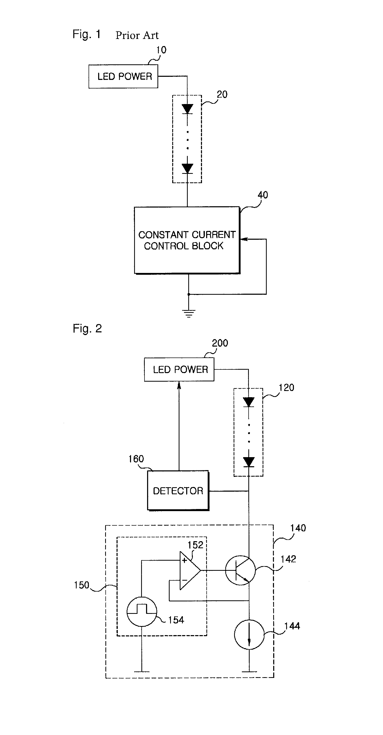
[0020]FIG. 2 is a schematic circuit diagram illustrating an LED driving circuit according to an exemplary embodiment of the present invention.

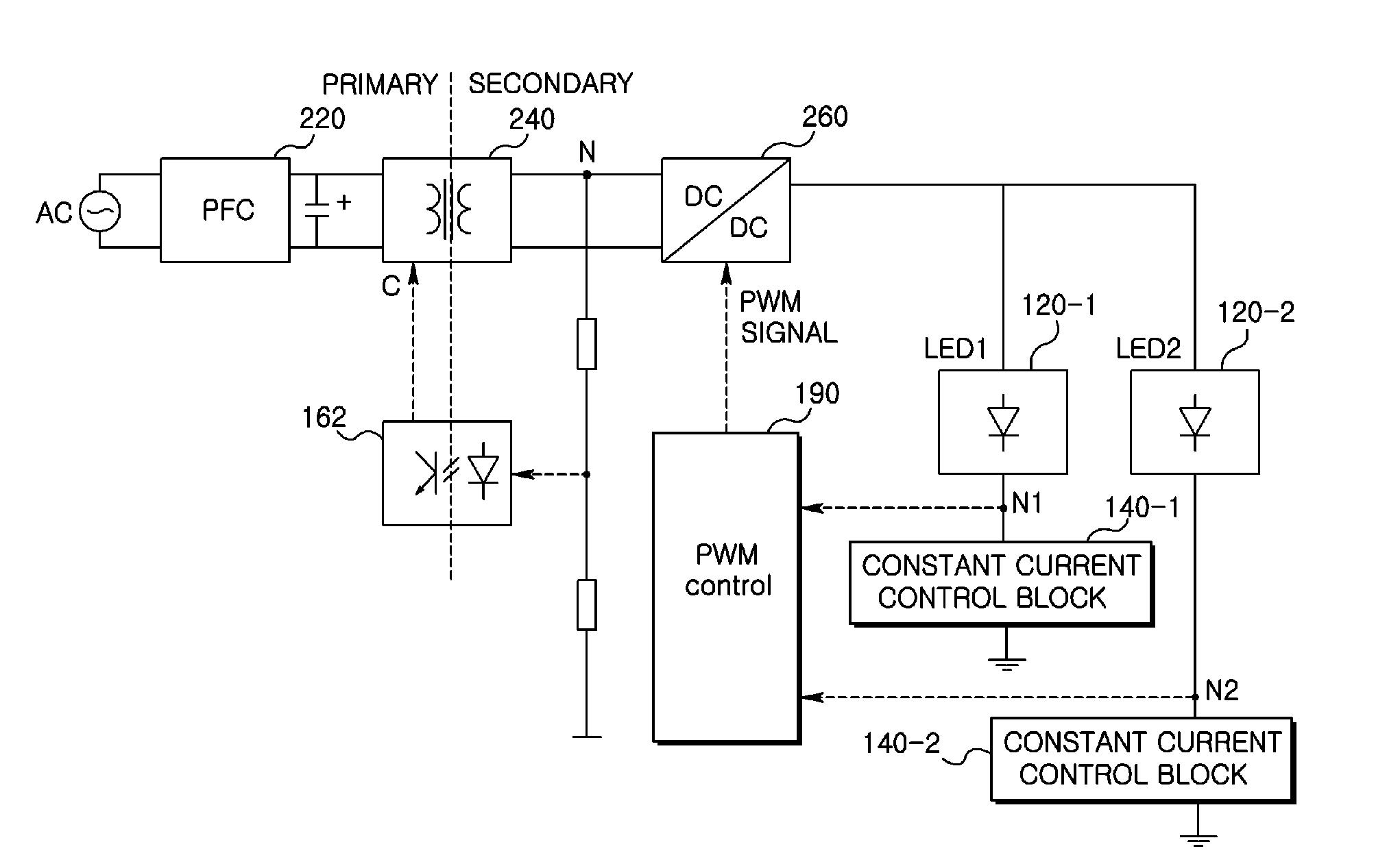
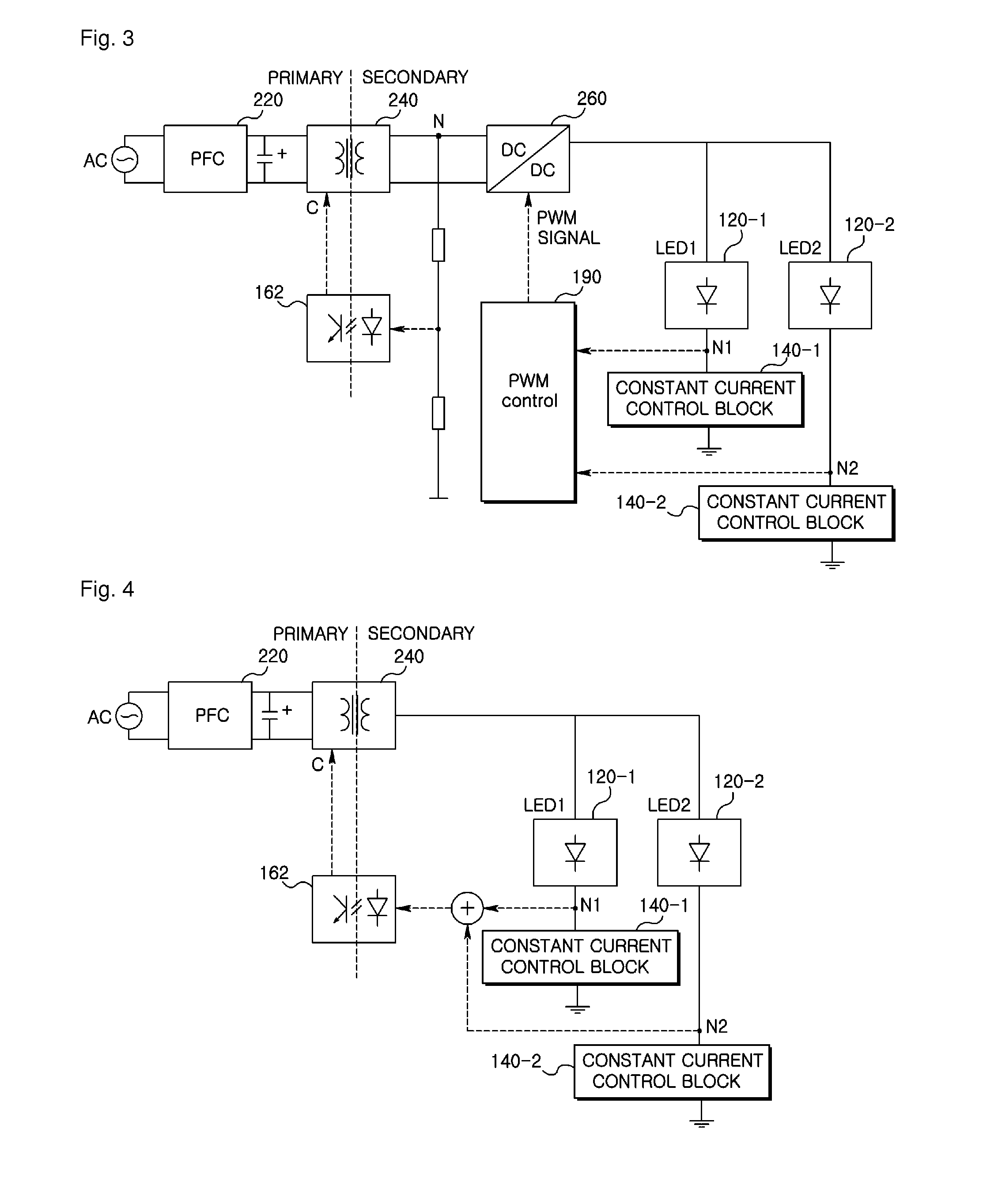
[0021]The LED (Light Emitting device) driving circuit may include at least two LED strings (120); at least two constant current control blocks (140) for respectively controlling a current path of the at least two LED strings; a detector (160) for detecting a voltage in the at least two constant current control blocks; and a power supply (200) for supplying a driving power to the at least two LED strings (120) in response to the detected voltage.

[0022]The constant current control block (140) may include a constant current source (144) causing a constant current to flow in a current path of the LED strings (120), a linear element (142) providing a variable resistance component to the current path of the LED string (120), and a feedback control element (150) controlling a resistance value of the linear element according to an electrical character...


PUM


Abstract

An LED (Light Emitting device) driving circuit is disclosed, the circuit characterized by: at least two LED strings (120); at least two constant current control blocks (140) for respectively controlling a current path of the at least two LED strings; a detector (160) for detecting a voltage in the at least two constant current control blocks; and a power supply (200) for supplying a driving power to the at least two LED strings (120) in response to the detected voltage.

Description

TECHNICAL FIELD[0001]The present invention relates to an LED driving circuit mounted with a constant current control means.BACKGROUND ART[0002]LED light source device comprised of a plurality of LED (Light Emitting Diode) strings is rapidly propagated for a wider use in lighting devices and backlight assemblys for LCD panel.[0003]Generally, an LED having a high brightness may be used for various application devices including backlight assemblies for LCD, monitors and televisions (hereinafter collectively referred to as “monitor”). The LEDs applied in a large-sized monitor are generally implemented in one or more strings connected in series.[0004]In order to apply a backlight assembly to the LCD monitor, one of two basic technologies are employed. A first technology is to use one or more strings comprised of a white LED, where the white LED generally includes a blue LED having a fluorescent material. The fluorescent material absorbs the blue light generated by the LED to emit a white...

Claims


Application Information

Patent Timeline
Patent Type & Authority Patents(United States)
IPC IPC(8): H05B37/00H05B44/00
CPCH05B45/46Y02B20/30H05B45/3725H05B45/44H05B45/48
Inventor KIM, SUNGEUN
Owner LG INNOTEK CO LTD
Learn More