
Miniaturized optical fiber drop cable

a technology of optical fiber drop cable and drop cable, which is applied in the direction of thin material handling, metal-working equipment, instruments, etc., can solve the problems of damage to delicate fibers, difficulty in accessing fibers or fibers,

Active Publication Date: 2015-01-27
COMMSCOPE INC
View PDF17 Cites 5 Cited by
  • Summary
  • Abstract
  • Description
  • Claims
  • Application Information

AI Technical Summary

Problems solved by technology

The drop cables, as typically formed in the background art, yield structures wherein it can be difficult to access the fiber or fibers when the cable is terminated to a connector.
The use of such tools near the fibers can damage the delicate fibers.

Method used


Image

  • Miniaturized optical fiber drop cable
  • Miniaturized optical fiber drop cable
  • Miniaturized optical fiber drop cable

Examples


Embodiment Construction

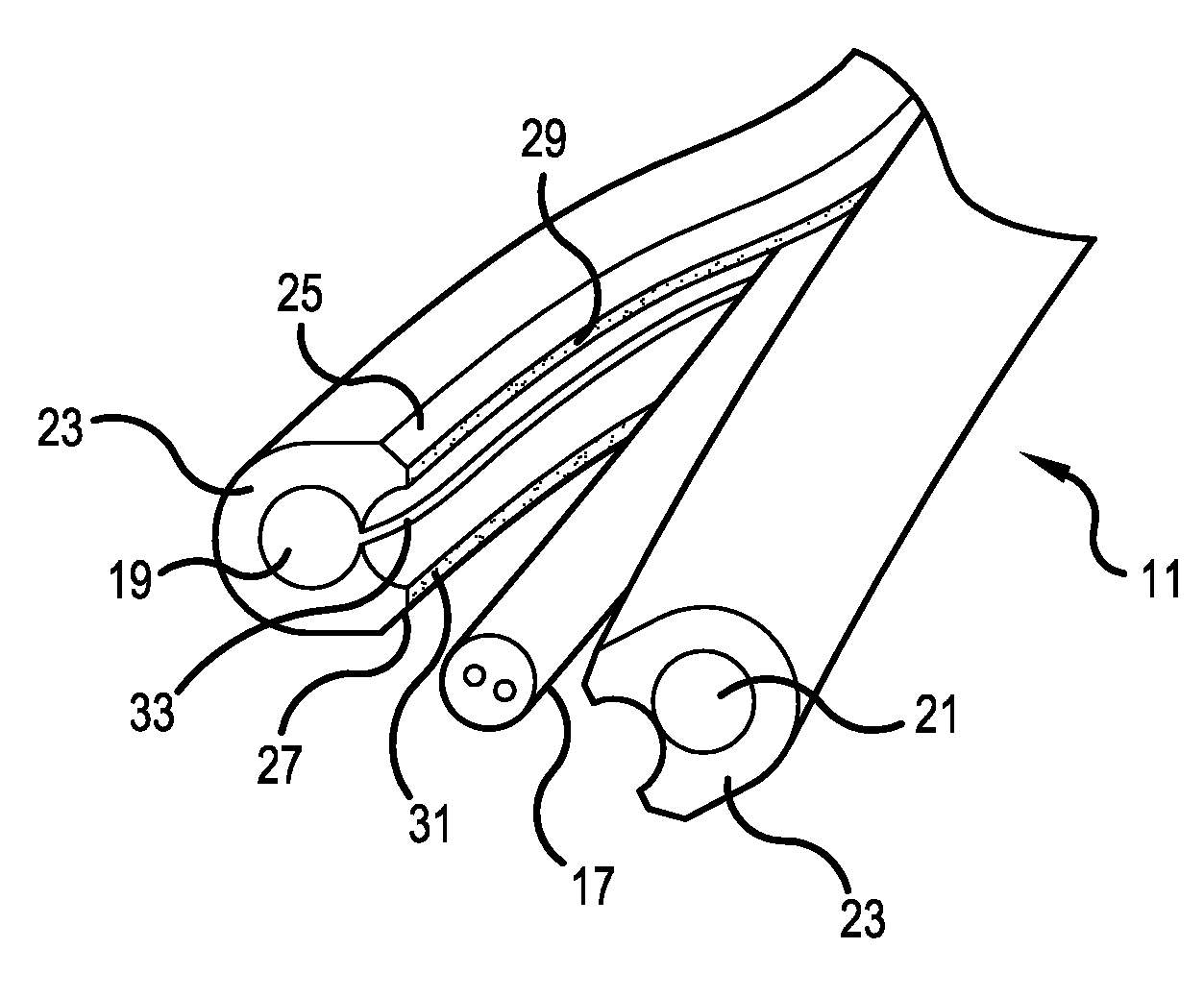
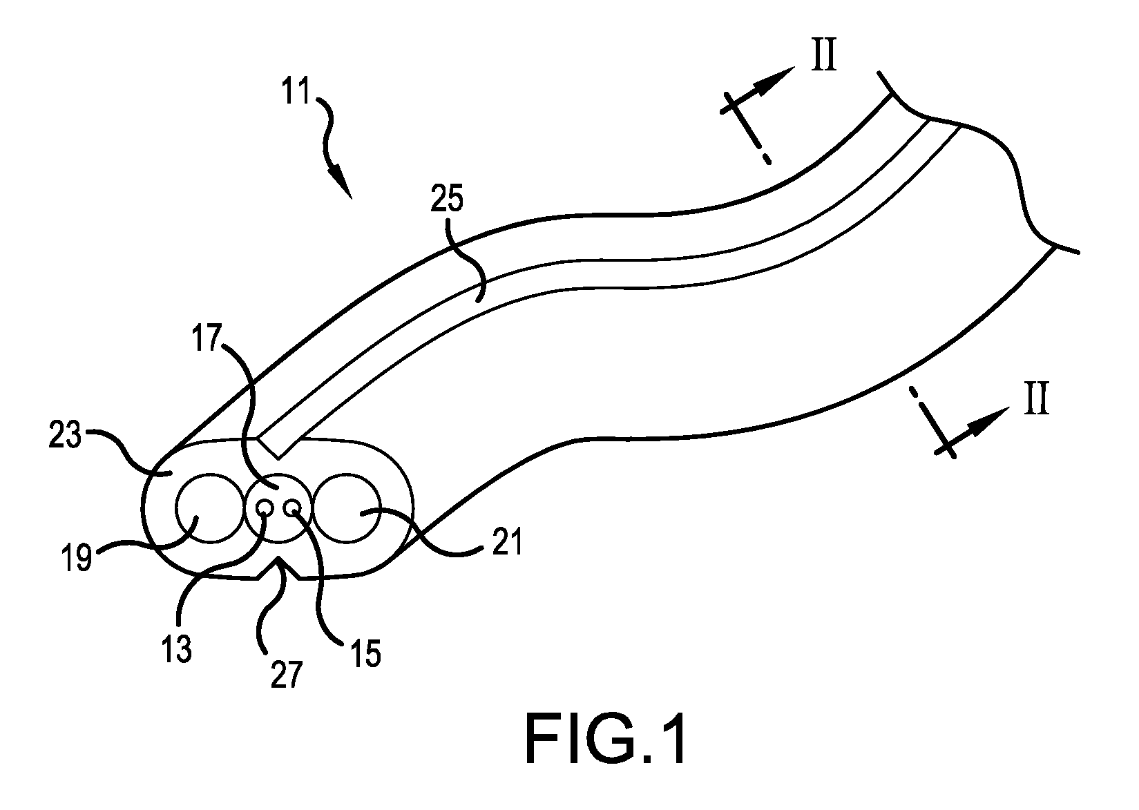
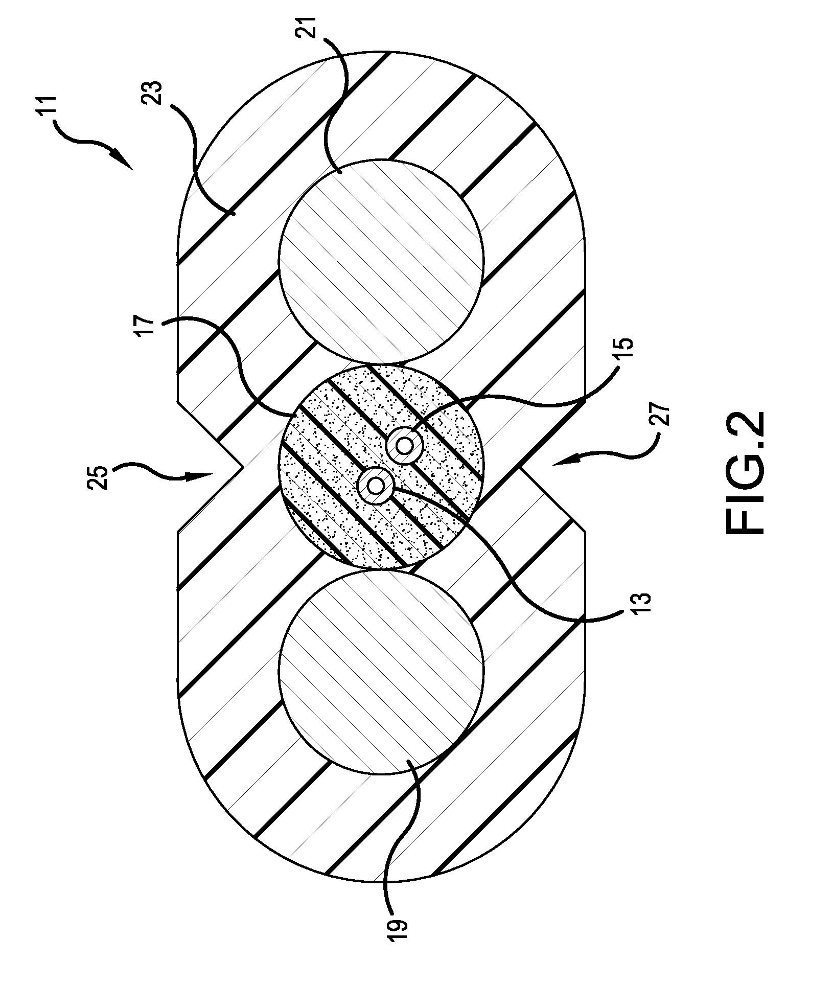
[0024]The present invention now is described more fully hereinafter with reference to the accompanying drawings, in which embodiments of the invention are shown. This invention may, however, be embodied in many different forms and should not be construed as limited to the embodiments set forth herein; rather, these embodiments are provided so that this disclosure will be thorough and complete, and will fully convey the scope of the invention to those skilled in the art.

[0025]Like numbers refer to like elements throughout. In the figures, the thickness of certain lines, layers, components, elements or features may be exaggerated for clarity. Broken lines illustrate optional features or operations unless specified otherwise.

[0026]The terminology used herein is for the purpose of describing particular embodiments only and is not intended to be limiting of the invention. Unless otherwise defined, all terms (including technical and scientific terms) used herein have the same meaning as c...


PUM


Abstract

A fiber optic cable includes first and second optical fibers. A fiber section surrounds the fibers and is formed of a first material. First and second strength members are adjacent to the fiber section on opposite sides thereof. A jacket surrounds the first and second strength members and fiber section. The jacket is formed of a second material, stronger than the first material and which does not adhere to the first material. The jacket may be manually torn open to access the fiber section. The fiber section may be manually pinched and stripped cleanly from the fibers. The fiber section acts as a cocoon to protect the fibers when the jacket is opened and cleanly pulls off of the fibers by manual force.

Description

[0001]This application claims the benefit of U.S. Provisional Application No. 61 / 558,341, filed Nov. 10, 2011, the entire contents of which are herein incorporated by reference.BACKGROUND OF THE INVENTION[0002]1. Field of the Invention[0003]The present invention relates to an optical fiber drop cable, and more particularly to an inexpensive, fiber drop cable having structural characteristics permitting safe, manual access to the fibers in the cable.[0004]2. Description of the Related Art[0005]Related art may be seen in U.S. Published Application 2003 / 0228116 and U.S. Pat. Nos. 5,448,670 and 7,397,992, all of which are incorporated herein by reference.SUMMARY OF THE INVENTION[0006]The drop cables, as typically formed in the background art, yield structures wherein it can be difficult to access the fiber or fibers when the cable is terminated to a connector. Cutting or scrapping tools are typically required to remove a jacketing material away of the area of the fibers. The use of such...

Claims


Application Information

Patent Timeline
Patent Type & Authority Patents(United States)
IPC IPC(8): G02B6/44G02B6/245
CPCG02B6/4429G02B6/4403G02B6/4495G02B6/4479G02B6/245G02B6/4471Y10T225/10G02B6/4431
Inventor LICHTENWALNER, JOSEPH J.SHINOSKI, JARRETT S.LOC, VOBURCH, SHAWN L.
Owner COMMSCOPE INC
Learn More