Vehicle infrared projection device

a technology of infrared projection and vehicle, which is applied in the direction of fixed installation, lighting support devices, lighting and heating apparatus, etc., can solve the problems of inability to install infrared lighting aftermarket, limited applicability, and detection devices, so as to improve traffic safety and improve traffic safety

Inactive Publication Date: 2015-02-03
E LEAD ELECTRONICS
View PDF3 Cites 3 Cited by
  • Summary
  • Abstract
  • Description
  • Claims
  • Application Information

AI Technical Summary

Benefits of technology

[0009]In view of this, in order to improve the traffic safety, the inventor finally completed the vehicle infrared projection device of the present invention, namely, the object of the present invention is to provide a vehicle infrared projection device, which is especially applicable for observing the long-distance road condition at night or poor weather, to thereby improve the traffic safety.
[0031]The vehicle infrared projection device may improve the observation distance of the road condition to achieve the requirement of long distance (100 meters or more). And, the retaining clip is used to fix the device body below or above the license plate bracket of the vehicle, so it may applicable for installing on all kinds of vehicles. Therefore, the technical means provided by the present invention may effectively solve the drawbacks of the conventional ones, to thereby improve the traffic safety.

Problems solved by technology

In order to avoid causing visual interference to front coming cars, dipped headlights are commonly used during driving, but the lighting distance of the dipped headlights is shorter, within about 30 meters, thus a driver who pay attention to night vision safety may install an infrared headlight in the vehicle additionally to improve insufficient lighting.
1. The design of using the infrared headlights to improve insufficient lighting must be planned during designing the vehicle, or there is no position to install it, so that the infrared lighting cannot be installed in aftermarket.
2. The infrared headlight may be installed above a fog light, but the position and the height of the fog light in each vehicle are different, so the applicability is very limited.
3. According to the related infrared vehicle equipments in the market recently, in the implementation, the infrared technology is mostly combined with alarm devices, the object is to remind a driver to keep a safe distance through the alarm function of alarm devices. Strictly, this kind of equipments may be considered as a traffic detector, they are used to remind the driver to keep a car safe distance. However, an important fact is ignored in the known technology and applications, that since the field of vision is limited when at night or in bad weather, what the driver really needs is the observation of far distance road conditions, not the short distance (within 30 meters) warning alarm. These short distance alert detector cannot meet the needs of drivers. Otherwise, drivers often cannot make a good emergency response in a very short period of time when alerting, especially under high-speed driving, the vehicle may rush the alert effective safe distance in just 1, 2 seconds. In order to overcome the possible danger, the only way is to raise the distance of observing road condition, to let drivers have enough time to react to thereby ensure traffic safety. For this reason, the infrared detecting device with the alert design in the recent market is not ideal driving auxiliary device.

Method used


Image

  • Vehicle infrared projection device
  • Vehicle infrared projection device
  • Vehicle infrared projection device

Examples


first embodiment

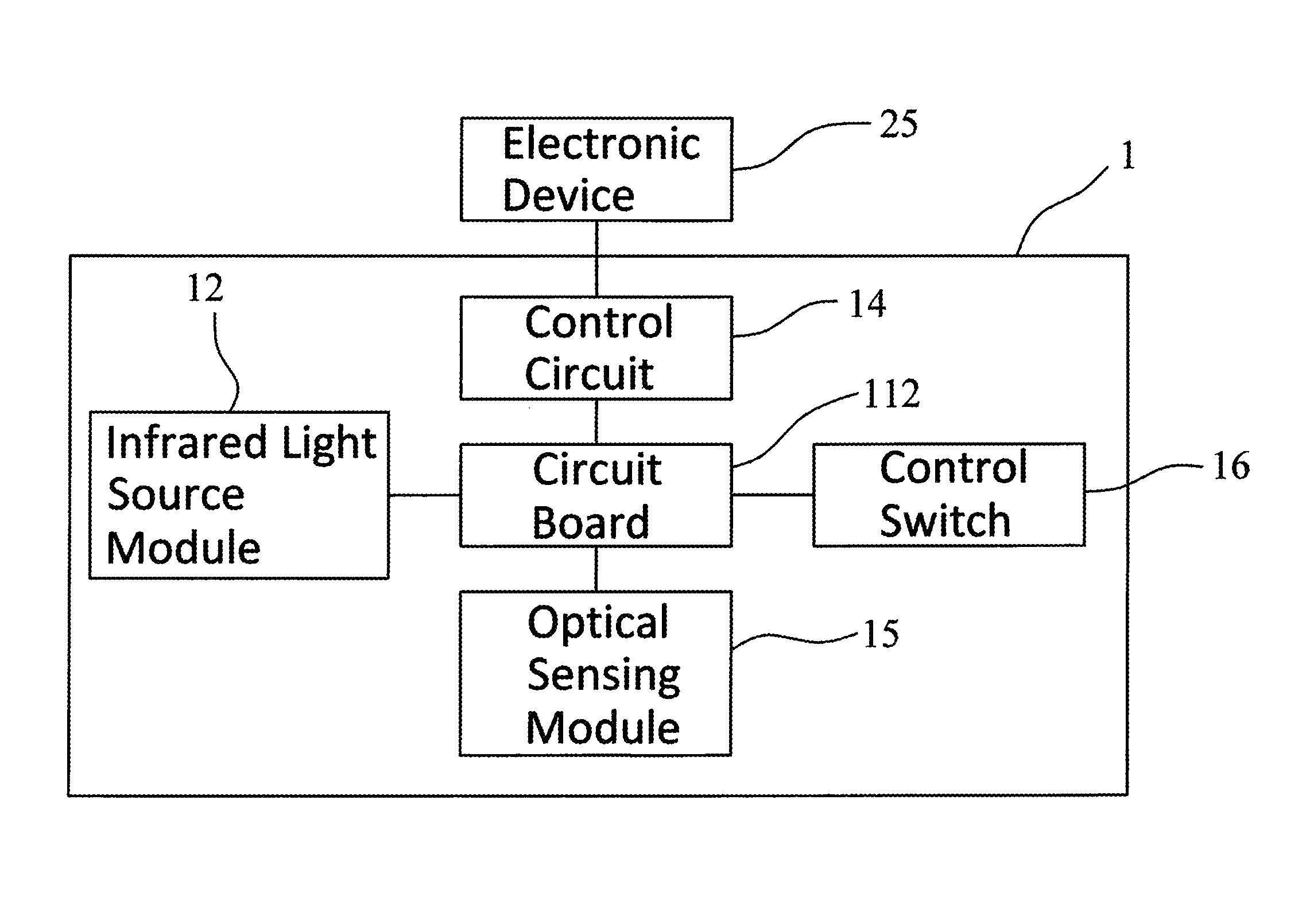
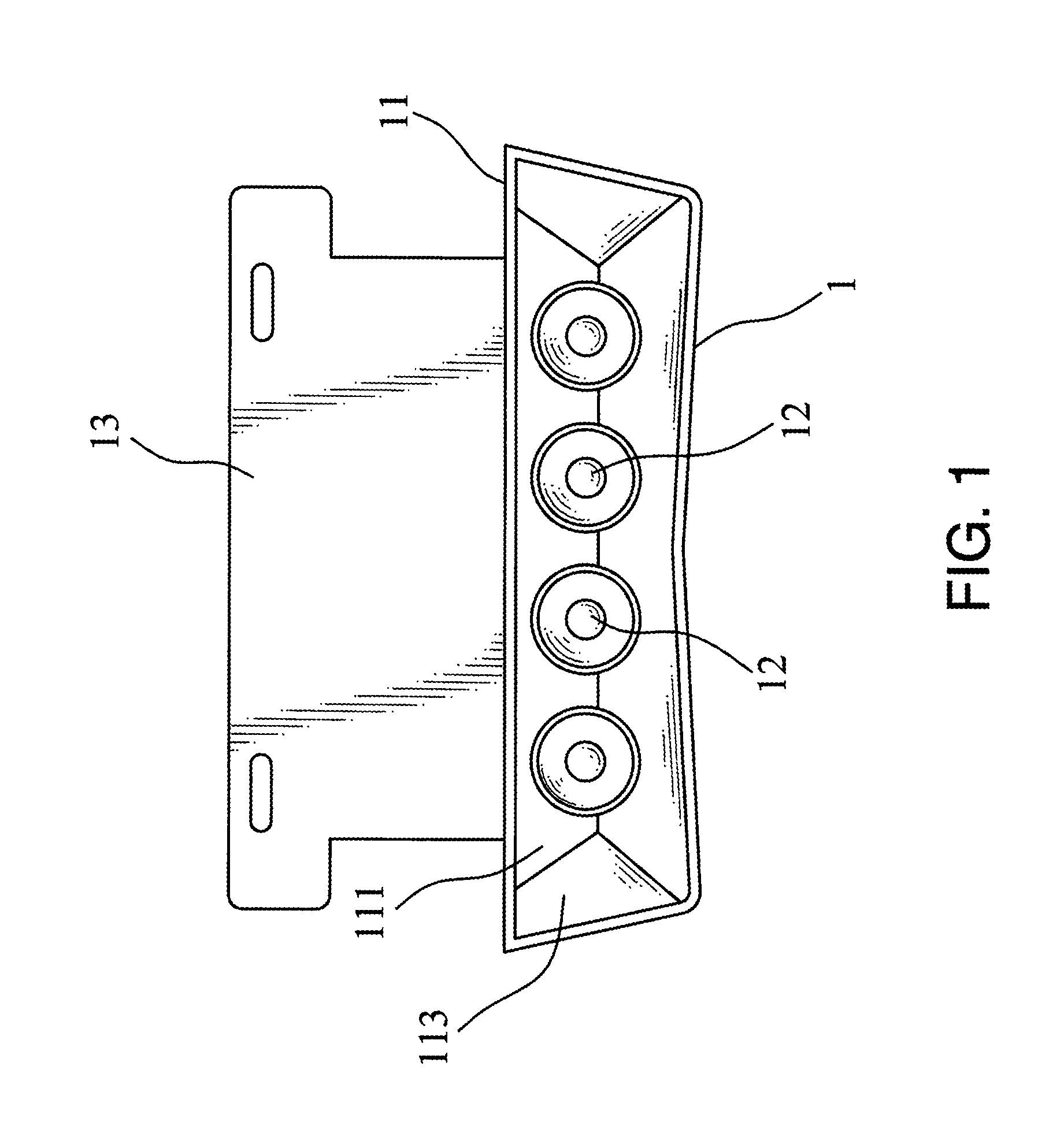
[0039]As shown in FIG. 1 and FIG. 2, the vehicle infrared projection device 1 of the present invention includes a device body 11, an infrared light source module 12 and a retaining clip 13 (please refer to FIG. 3, FIG. 4, FIG. 5 simultaneously), wherein:

[0040]The device body 11, a containing space 111 is set inside it, a circuit board 112 is set in the containing space 111, and a projection opening 113 is set in the front of the device body 11.

[0041]The infrared light source module 12, which is electrically connected to the circuit board 112, the infrared light source module 12 is set in the containing space 111 of the device body 11, the infrared light source module 12 includes at least an infrared light source 121, the projection direction of the infrared light source 121 is the direction of the projection opening 113 of the device body 11.

[0042]The retaining clip 13, which is used to fix the device body 11 below 22 (as shown in FIG. 1, FIG. 3) or above 23 (as shown in FIG. 4, FIG...

second embodiment

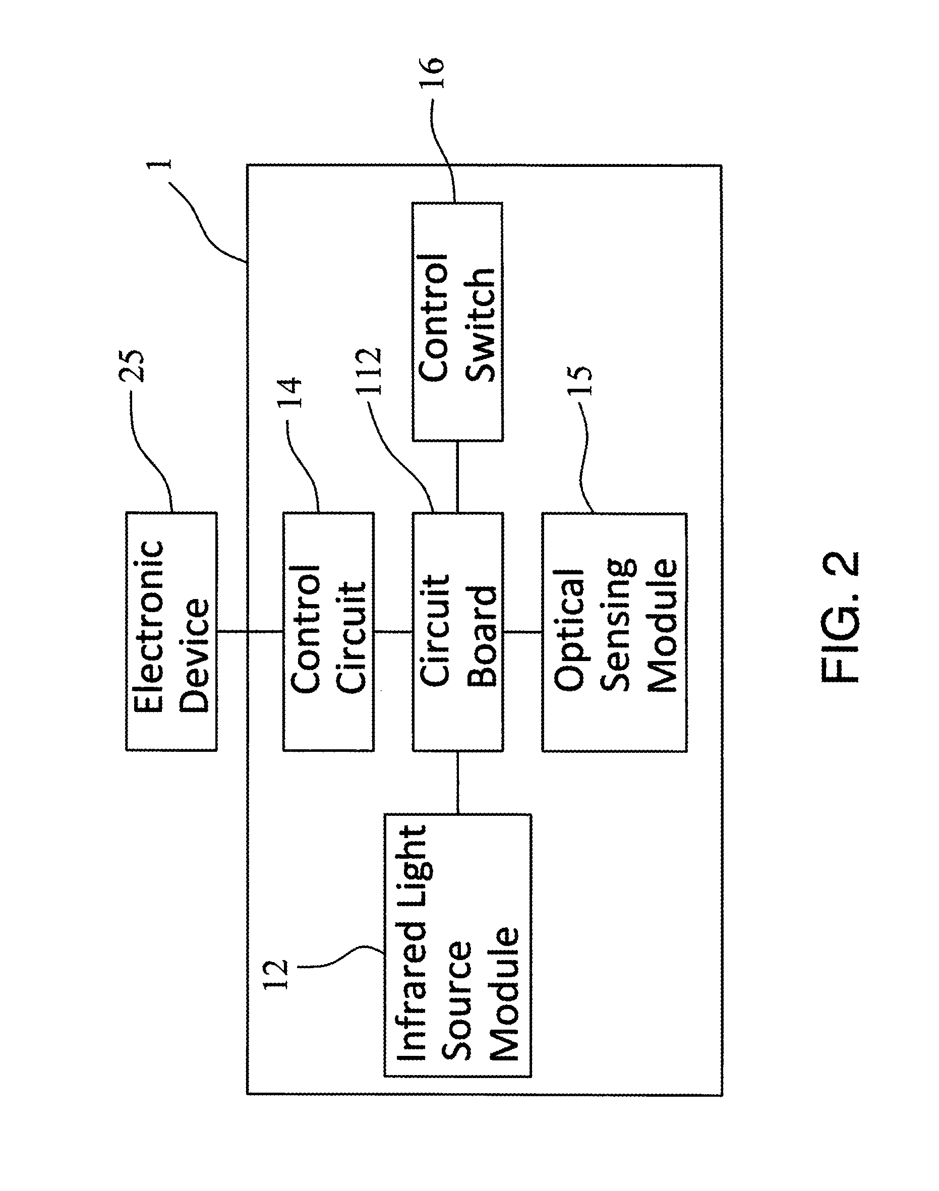
[0048]As shown in FIGS. 1 to 5, the vehicle infrared projection device 1 of the present invention includes a device body 11, an infrared light source module 12, a retaining clip 13 and an optical sensing module 15, wherein:

[0049]The device body 11, a containing space 111 is set inside it, a circuit board 112 is set in the containing space 111, a projection opening 113 is set in the front of the device body 11.

[0050]The infrared light source module 12, which is electrically connected to the circuit board 112, the infrared light source module 12 is set in the containing space 111 of the device body 11, the infrared light source module 12 includes at least an infrared light source 121, the projection direction of the infrared light source 121 is the direction of the projection opening 113 of the device body 11.

[0051]The retaining clip 13, which is used to fix the device body 11 below 22 (as shown in FIG. 1, FIG. 3) or above 23 (as shown in FIG. 4, FIG. 5) a license plate bracket 21 of ...

third embodiment

[0056]As shown in FIGS. 1 to 4, the vehicle infrared projection device 1 of the present invention includes a device body 11, an infrared light source module 12, a retaining clip 13 and a control switch 16, wherein:

[0057]The device body 11, a containing space 111 is set inside it, a circuit board 112 is set in the containing space 111, a projection opening 113 is set in the front of the device body 11.

[0058]The infrared light source module 12, which is electrically connected to the circuit board 112, the infrared light source module 12 is set in the containing space 111 of the device body 11, the infrared light source module 12 includes at least an infrared light source 121, the projection direction of the infrared light source 121 is the direction of the projection opening 113 of the device body 11.

[0059]The retaining clip 13, which is used to fix the device body 11 below 22 (as shown in FIG. 1, FIG. 3) or above 23 (as shown in FIG. 4, FIG. 5) a license plate bracket 21 of a vehicle...


PUM


Abstract

A vehicle infrared projection device, includes a device body, an infrared light source module and a retaining clip, wherein the retaining clip is used to retain the device body below or above a vehicle license plate bracket, a projection opening set on the device body is provided as the projection direction of the infrared light source of the infrared light source module, the focus type lens of the infrared light source module limit an included angle of the projection angle of the infrared light source to 6-15 degree. By the composition of the above elements, the present invention may provide assistance for observing the long-distance road condition at night or poor weather, to thereby improve the traffic safety.

Description

BACKGROUND OF THE INVENTION[0001]1. Field of the Invention[0002]The invention relates to a vehicle infrared projection device and, more particularly, a vehicle infrared projection device to assisting a driver, especially applicable for observing the long-distance road condition at night or poor weather, to thereby improve the traffic safety.[0003]2. Brief Description of the Related Art[0004]General car lights are visible light lamps. In order to avoid causing visual interference to front coming cars, dipped headlights are commonly used during driving, but the lighting distance of the dipped headlights is shorter, within about 30 meters, thus a driver who pay attention to night vision safety may install an infrared headlight in the vehicle additionally to improve insufficient lighting. Since infrared is invisible light that may not cause visual influence to drivers of coming cars, the infrared headlight may be made as the angle of high beams and the lighting distance may be effective...

Claims


Application Information

Patent Timeline
Patent Type & Authority Patents(United States)
IPC IPC(8): B60Q1/56B60Q1/04
CPCB60Q1/04B60Q1/18B60Q2900/10
Inventor CHEN, STEPHEN
Owner E LEAD ELECTRONICS
Why Eureka
Try Eureka