
Battery pack having conductive line holders

a technology of conductive line holders and batteries, which is applied in the direction of current conducting connections, secondary cells servicing/maintenance, cell components, etc., can solve the problems of electrical shorts, conductive wires may be easily disconnected from the solder joints, and it is impossible for the disconnected conductive lines to be stably fixed to the predetermined areas, so as to prevent an electrical short

Active Publication Date: 2015-02-03
SAMSUNG SDI CO LTD
View PDF22 Cites 0 Cited by
  • Summary
  • Abstract
  • Description
  • Claims
  • Application Information

AI Technical Summary

Benefits of technology

The present invention provides a battery pack that stops a disconnected conductive line from contacting a battery cell or circuit of a protective circuit module, which could cause an electrical short. This prevents the battery from being short-circuited and potentially causing damage or injury.

Problems solved by technology

A typical battery pack includes a set of battery cells, due to the limited capacity of an individual battery cell.
Since only portions of conductive wires, which are exposed from the ends of the conductive lines, are soldered to the conductive tabs, there is the risk that the conductive wires may be easily disconnected from the solder joints, when a strong external impact is applied to the battery pack.
This contact may cause an electrical short.
However, an electrolyte leaking from the battery cells weakens the adhesive strength of the fixing tapes, making it impossible for the disconnected conductive lines to be stably fixed to the predetermined areas.

Method used


Image

  • Battery pack having conductive line holders
  • Battery pack having conductive line holders
  • Battery pack having conductive line holders

Examples


Embodiment Construction

[0035]Reference will now be made in detail to the exemplary embodiments of the present invention, examples of which are illustrated in the accompanying drawings, wherein like reference numerals refer to the like elements throughout. The exemplary embodiments are described below, in order to explain the aspects of the present invention, by referring to the figures.

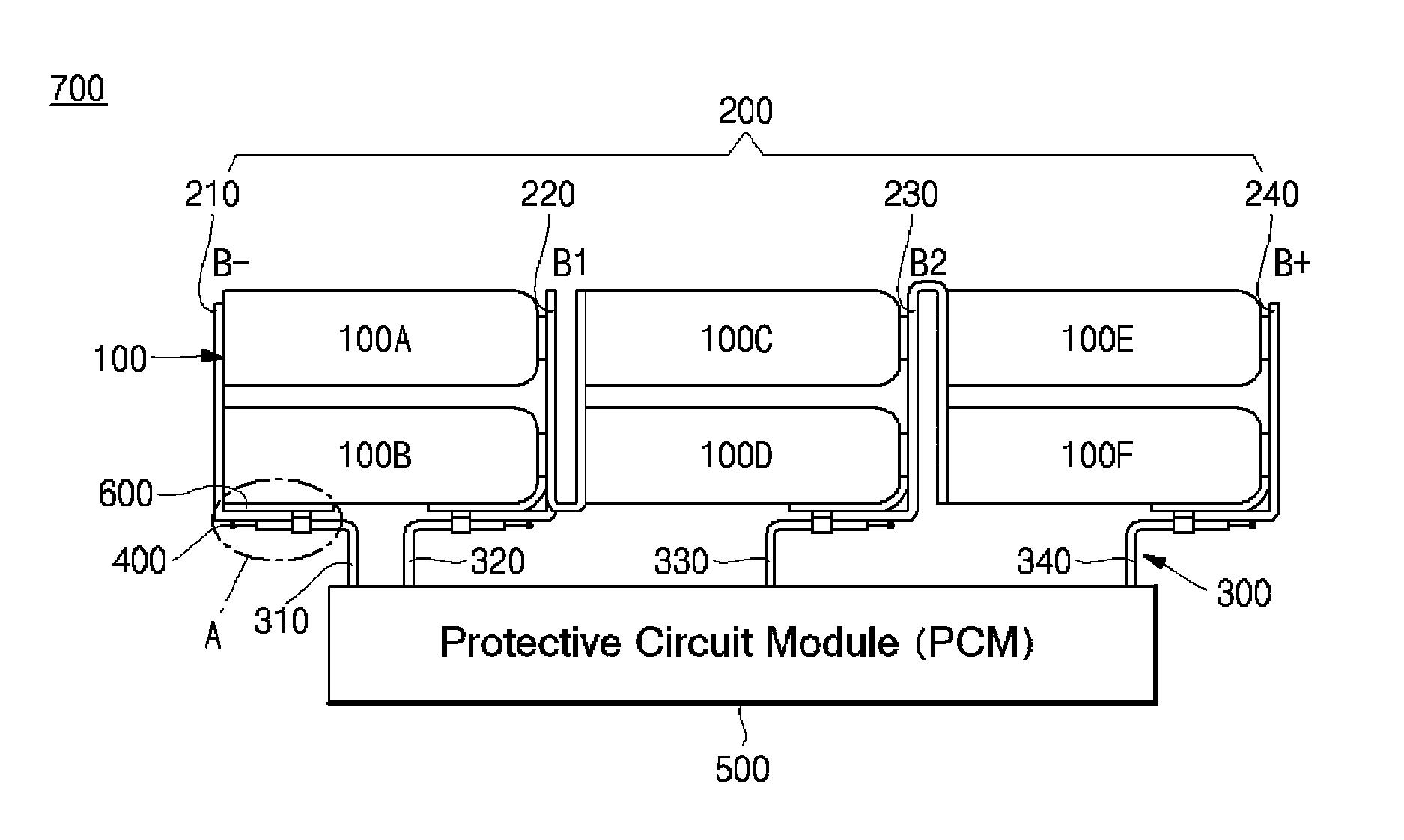
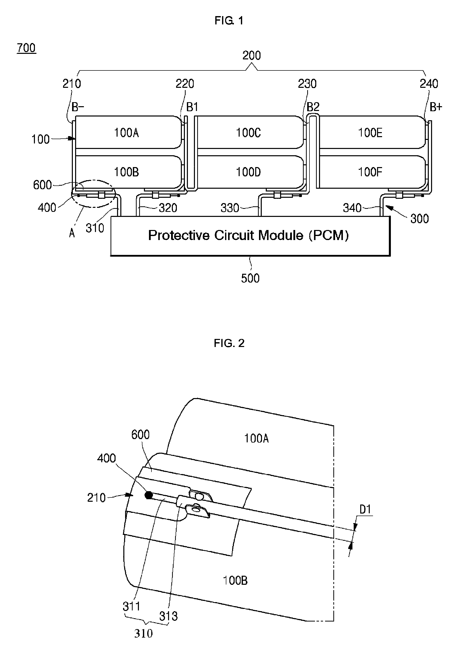
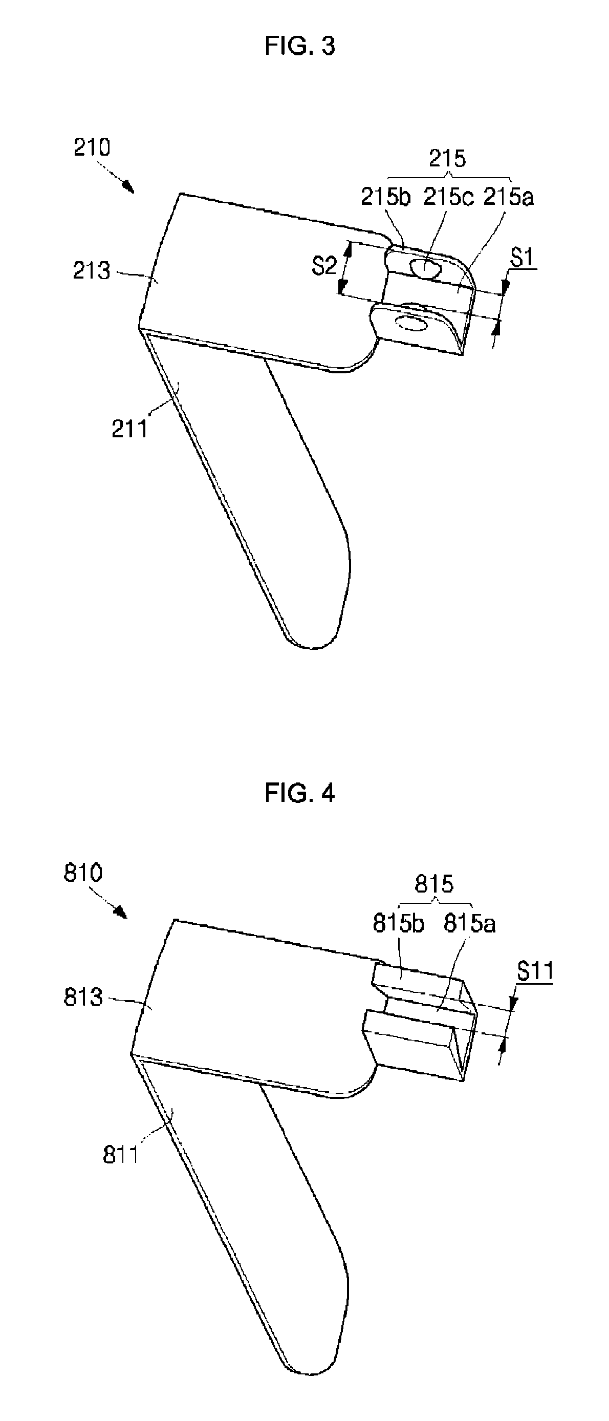
[0036]FIG. 1 is a schematic view illustrating the structure of a battery pack 700, according to an exemplary embodiment of the present invention, FIG. 2 is a perspective view illustrating portion ‘A’ of FIG. 1, and FIG. 3 is an enlarged perspective view illustrating a conductive tab 200 of FIG. 2. Referring to FIGS. 1 through 3, the battery pack 700 comprises a plurality of battery cells 100, the conductive tabs 200, conductive lines 300, solder joints 400, a protective circuit module 500, and insulating tapes 600.

[0037]First and second ends of the battery cells 100 have different polarities. In FIG. 1, the first ends are t...


PUM

PropertyMeasurementUnit
operating voltageaaaaaaaaaa
conductiveaaaaaaaaaa
thicknessaaaaaaaaaa

Abstract

A battery pack including: a plurality of battery cells; conductive tabs, each of which has a first portion electrically connected to at least one of the battery cells, and a second portion extending from the first portion; conductive lines electrically connected to the second portions of the conductive tabs; and a protective circuit module electrically connected to the conductive lines. Each of the conductive tabs includes a conductive line holding portion formed at the second portion, to fix the corresponding conductive line. Due to this constitution of the battery pack, the conductive lines are prevented from entirely escaping from the area of solder joints with the conductive tabs, after being disconnected from the solder joints. Therefore, the conductive lines do not come into contact with the battery cells or circuits of the protective circuit module.

Description

CROSS-REFERENCE TO RELATED APPLICATION[0001]This application claims the benefit of Korean Patent Application No. 10-2008-0098830, filed on Oct. 8, 2008, in the Korean Intellectual Property Office, the disclosure of which is incorporated herein, by reference.BACKGROUND OF THE INVENTION[0002]1. Field of the Invention[0003]Aspects of the present invention relate to a battery pack.[0004]2. Description of the Related Art[0005]Battery packs are widely used in portable electronic devices, such as notebook computers, personal digital assistants (PDAs), and camcorders. A typical battery pack includes a set of battery cells, due to the limited capacity of an individual battery cell.[0006]Specifically, a battery pack comprises a plurality of rechargeable battery cells, a protective circuit module (PCM), and conductive tabs and conductive lines electrically connecting the battery cells and the protective circuit module. The PCM includes a circuit to control the charge / discharge of the battery c...

Claims


Application Information

Patent Timeline
Patent Type & Authority Patents(United States)
IPC IPC(8): H01M2/24H01M50/529H01M10/42H01M50/50H01M50/569
CPCH01M2/20H01M10/425H01M50/50H01M50/569Y02E60/10H01M50/543H01M50/572
Inventor MOON, DEA YON
Owner SAMSUNG SDI CO LTD
Learn More