Zoom illumination system

Inactive Publication Date: 2015-02-03
POSTOVALOV VALDIS +1
View PDF48 Cites 12 Cited by
  • Summary
  • Abstract
  • Description
  • Claims
  • Application Information

AI Technical Summary

Benefits of technology

[0026]A yet further embodiment provides an illumination system comprising a plurality of radiation sources each operable to emit radiation over a di

Problems solved by technology

However, these illuminators generally do not provide sufficient light for narrow angle long-range viewing.
Thus, they are bulky as well as mechanically and electronical

Method used


Image

  • Zoom illumination system
  • Zoom illumination system
  • Zoom illumination system

Examples


Embodiment Construction

[0037]With the issues defined above in mind, one presently preferred embodiment comprises a zoom illumination system. The system does not require use of a zoom lens, and it does not require moving parts. The system may be used with digital and mechanical zoom processing or CCTV images to provide a zoom system with no moving parts.

[0038]As used herein, the term “illuminator” refers to an illumination device comprising one or more light sources, a power supply, and a controller or switch. As used herein, the term “light source” refers to one or more electrically coupled light emitters, for example a string of LEDs.

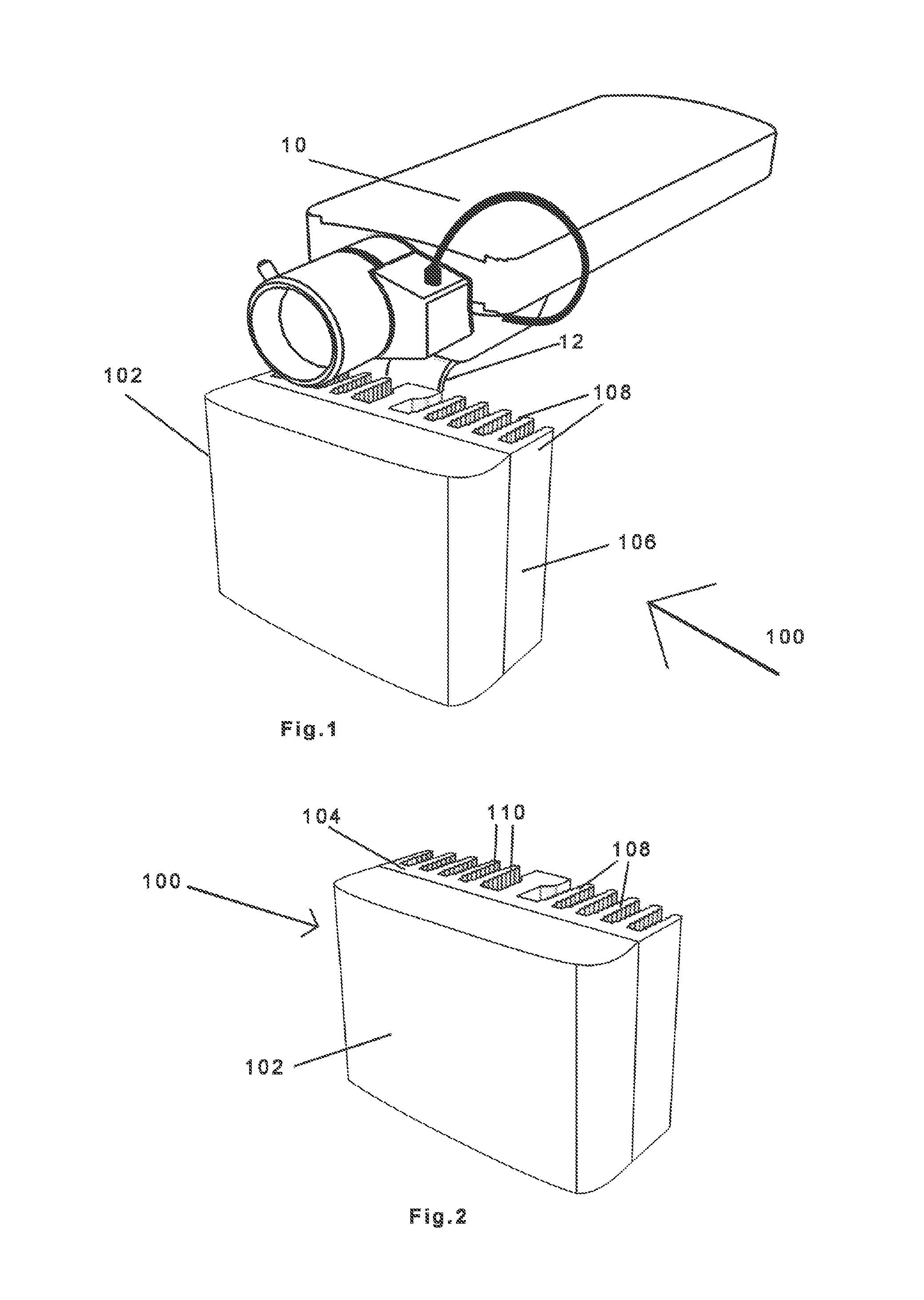
[0039]As shown in FIGS. 1-2, zoom illuminator 100 is mounted adjacent a camera 10, for example a CCTV camera, onto a support structure 12, in a manner that illuminator 100 and camera 10 can be moved together as a unit, such as for panning and tilting. In another embodiment, however, the camera 10 may be mounted to a support structure which extends from the illuminator 100. I...


PUM


Abstract

Zoom illumination system for use with closed circuit TV cameras in applications requiring long distance illumination, such as surveillance and night vision. The system includes multiple strings of LEDs, which may have additional lenses, with each LED string capable of providing illumination for a predetermined viewing angle. The LED strings can be switched on and off to provide illumination as desired.

Description

CROSS REFERENCE TO RELATED APPLICATIONS[0001]This application claims the benefit of U.S. Provisional Patent Application Ser. No. 61 / 471,003 of Valdis and Dmitry Postovalov, filed on Apr. 1, 2011, entitled “Zoom Illumination System,” which is included herein by reference in its entirety.FIELD OF THE INVENTION[0002]The present invention relates generally to an illumination system for use with closed circuit TV cameras, and more particularly to a zoom illumination system for use with closed circuit TV cameras in applications requiring long distance illumination.BACKGROUND OF THE INVENTION[0003]Closed circuit television (CCTV) systems are commonly used for video surveillance operations, such as for security applications and night vision. Traditional CCTV cameras operate mainly with the visible light spectrum and are blind in conditions of darkness, such as during the night or in enclosed spaces within buildings. CCTV cameras are available that can operate with either the visible light s...

Claims


Application Information

Patent Timeline
IPC IPC(8): H04N7/18G08B13/196H04N5/235
CPCH04N7/181H04N7/183H04N7/188G08B13/19656H04N5/235G08B13/196G03B15/05H04N7/18G03B2215/0567G03B2215/0592G03B2215/0571G08B13/19695H04N23/56H04N23/69H04N23/74H04N23/70
Inventor POSTOVALOV, VALDISPOSTOVALOV, DMITRY
Owner POSTOVALOV VALDIS
Why Eureka
Try Eureka