Supercharge Your Innovation With Domain-Expert AI Agents!

Sheet thickness detector and image forming apparatus including same

a detector and sheet thickness technology, applied in the direction of electrographic process apparatus, thin material processing, instruments, etc., can solve the problems of inability to accurately detect the displacement amount equal to the thickness of the sheet, complicated and/or costly configuration, and uneven detection

Inactive Publication Date: 2015-02-10
RICOH KK
View PDF11 Cites 4 Cited by
  • Summary
  • Abstract
  • Description
  • Claims
  • Application Information

AI Technical Summary

Benefits of technology

The solution provides accurate sheet thickness detection, enabling precise control of image forming process conditions and reducing manufacturing costs by simplifying the detector's configuration and preventing rotational fluctuation effects, thus enhancing the overall efficiency and reliability of image forming apparatuses.

Problems solved by technology

However, such optimization includes complicated and / or costly configurations, and provides uneven detection results.
Therefore, the amount of displacement by an amount equivalent to the thickness of the sheet may not be detected accurately.
Even though not having a configuration that directly detects the amount of displacement of the detection roller, the sheet thickness detector of this example has a configuration that detects an amount of displacement of a displacement member operating together with the detection roller, and therefore is negatively affected by rotational fluctuation of the detection roller.
Further, this configuration is so complicated to install in a compact image forming apparatus, which is likely to increase its manufacturing cost.
However, the complicated configuration of the displacement member makes it difficult to provide the displacement member in a space-saving device or apparatus such as an image forming apparatus, which is also likely to increase the cost.

Method used


Image

  • Sheet thickness detector and image forming apparatus including same
  • Sheet thickness detector and image forming apparatus including same
  • Sheet thickness detector and image forming apparatus including same

Examples


Embodiment Construction

[0034]It will be understood that if an element or layer is referred to as being “on”, “against”, “connected to” or “coupled to” another element or layer, then it can be directly on, against, connected or coupled to the other element or layer, or intervening elements or layers may be present. In contrast, if an element is referred to as being “directly on”, “directly connected to” or “directly coupled to” another element or layer, then there are no intervening elements or layers present. Like numbers referred to like elements throughout. As used herein, the term “and / or” includes any and all combinations of one or more of the associated listed items.

[0035]Spatially relative terms, such as “beneath”, “below”, “lower”, “above”, “upper” and the like may be used herein for ease of description to describe one element or feature's relationship to another element(s) or feature(s) as illustrated in the figures. It will be understood that the spatially relative terms are intended to encompass...


PUM


Abstract

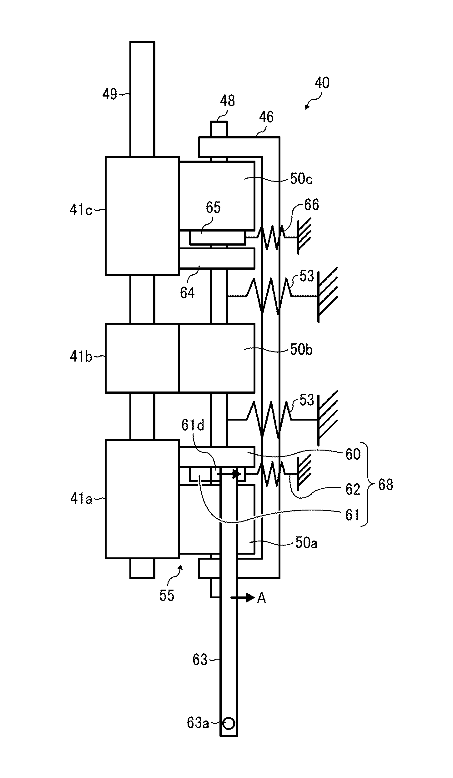
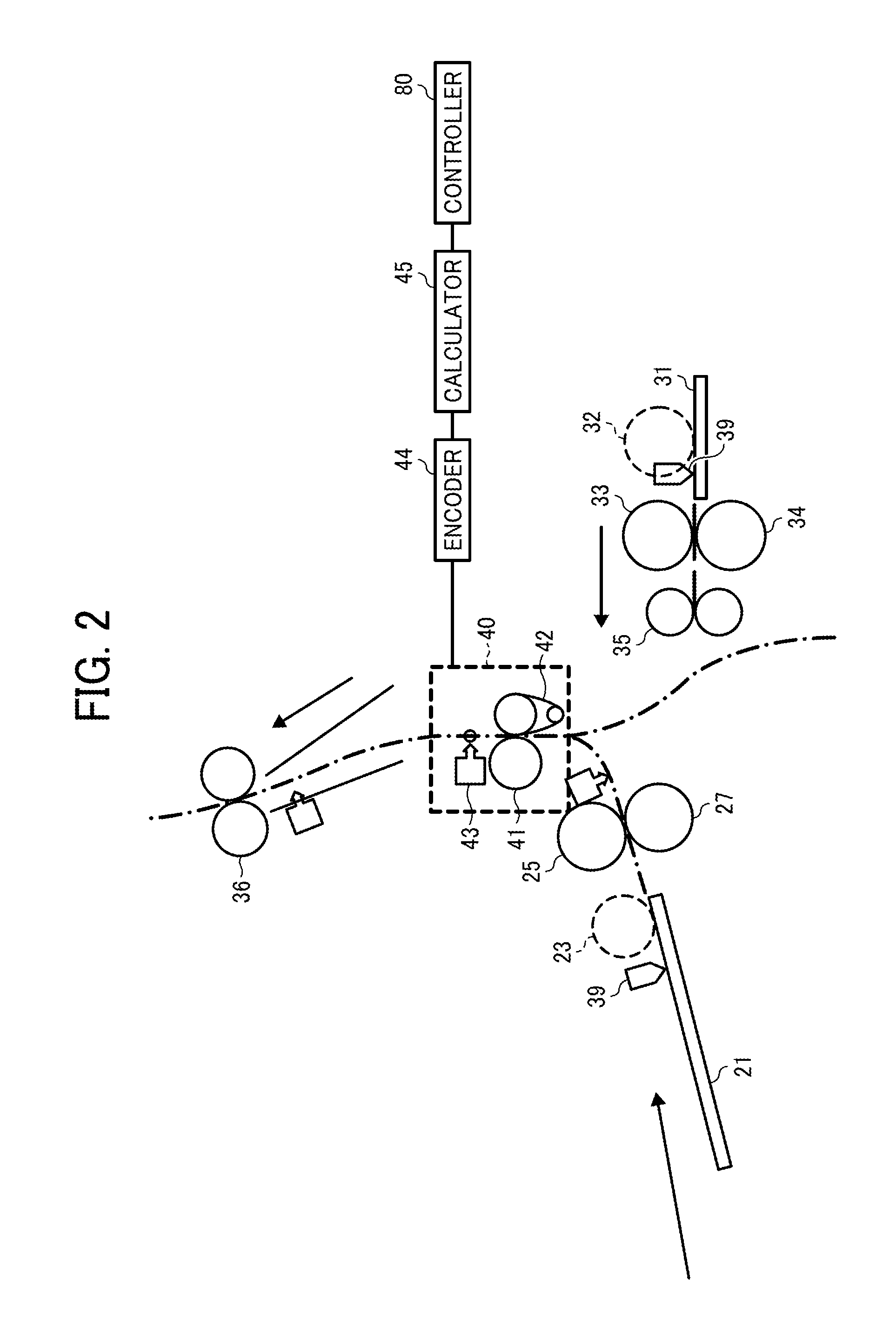
A sheet thickness detector incorporated in an image forming apparatus includes a sheet conveying member to rotate and convey a sheet in a sheet conveyance direction, a driven sheet conveying member to contact the sheet conveying member and form at least one first transfer nip therebetween in a lateral direction and to displace by an amount equivalent to a thickness of the sheet passing through the first transfer nip and rotated with the sheet conveying member in the sheet conveyance direction, a displacement member to contact the sheet conveying member and form a second transfer nip smaller than the first transfer nip in the lateral direction and to displace by an amount equivalent to the thickness of the sheet passing through the second transfer nip and supported at a support member, and a displacement amount detector to detect an amount of displacement of the displacement member.

Description

CROSS-REFERENCE TO RELATED APPLICATIONS[0001]This patent application is based on and claims priority pursuant to 35 U.S.C. §119 to Japanese Patent Application Nos. 2012-155353, filed on Jul. 11, 2012 and 2012-280927, filed on Dec. 25, 2012 in the Japan Patent Office, the entire disclosures of which are hereby incorporated by reference herein.BACKGROUND[0002]1. Technical Field[0003]Embodiments of the present invention generally relate to a sheet thickness detector to detect the thickness of a sheet to be supplied, and an image forming apparatus incorporating the sheet thickness detector.[0004]2. Related Art[0005]In image forming apparatuses such as printers, copiers, and facsimile machines forming an image on a sheet of recording medium, image forming conditions are optimized according to sheet thickness for producing a high-quality image.[0006]However, such optimization includes complicated and / or costly configurations, and provides uneven detection results.[0007]In a transfer proce...

Claims


Application Information

Patent Timeline
Patent Type & Authority Patents(United States)
IPC IPC(8): B65H5/02B65H5/04B65H7/12G03G15/00
CPCB65H7/12G03G15/5029G03G2215/00628G03G2215/00738B65H7/14B65H2404/144B65H5/068B65H7/20
Inventor WAKABAYASHI, YUUTAKENAKA, RYOSATOH, MASASHINISHIZAKI, SHINGOOZAKI, YUSUKEIKEDA, YUJIOKAMURA, HIROSHIFUNADA, NAOHIROKONDOH, TOMOHIDE
Owner RICOH KK
Features
  • R&D
  • Intellectual Property
  • Life Sciences
  • Materials
  • Tech Scout
  • Unparalleled Data Quality
  • Higher Quality Content
  • 60% Fewer Hallucinations
Learn More