
Systems, methods, and apparatuses to image a sample for biological or chemical analysis

a technology of biological or chemical analysis and image, applied in the field of assay systems, can solve the problems of limited capabilities of systems configured to perform such protocols and may not be cost-effective, and achieve the effect of cost-effectiveness and cost-effectiveness

Active Publication Date: 2015-02-10
ILLUMINA INC
View PDF94 Cites 262 Cited by
  • Summary
  • Abstract
  • Description
  • Claims
  • Application Information

AI Technical Summary

Benefits of technology

The patent describes a fluidic device for analyzing samples, as well as a holder for positioning the device. The device includes a flow cell with a reception space that is sized and shaped to hold the sample. The device also includes a gasket that is positioned over the flow cell, with the gasket having compressible material. The gasket is designed to align with the inlet and outlet ports of the flow cell. The holder for the device includes a support structure and a cover assembly that is removably mounted over the device. The cover assembly includes a cover housing with a viewing space that is positioned above the device. The device also includes an optical assembly with a base plate and a component-receiving space that holds an optical component. The optical component has an optical surface that is positioned in a predetermined orientation. The technical effects of the patent include improved accuracy in positioning the sample for analysis and improved alignment of the optical components.

Problems solved by technology

However, systems configured to perform such protocols may have limited capabilities and may not be cost-effective.

Method used


Image

  • Systems, methods, and apparatuses to image a sample for biological or chemical analysis
  • Systems, methods, and apparatuses to image a sample for biological or chemical analysis
  • Systems, methods, and apparatuses to image a sample for biological or chemical analysis

Examples


Embodiment Construction

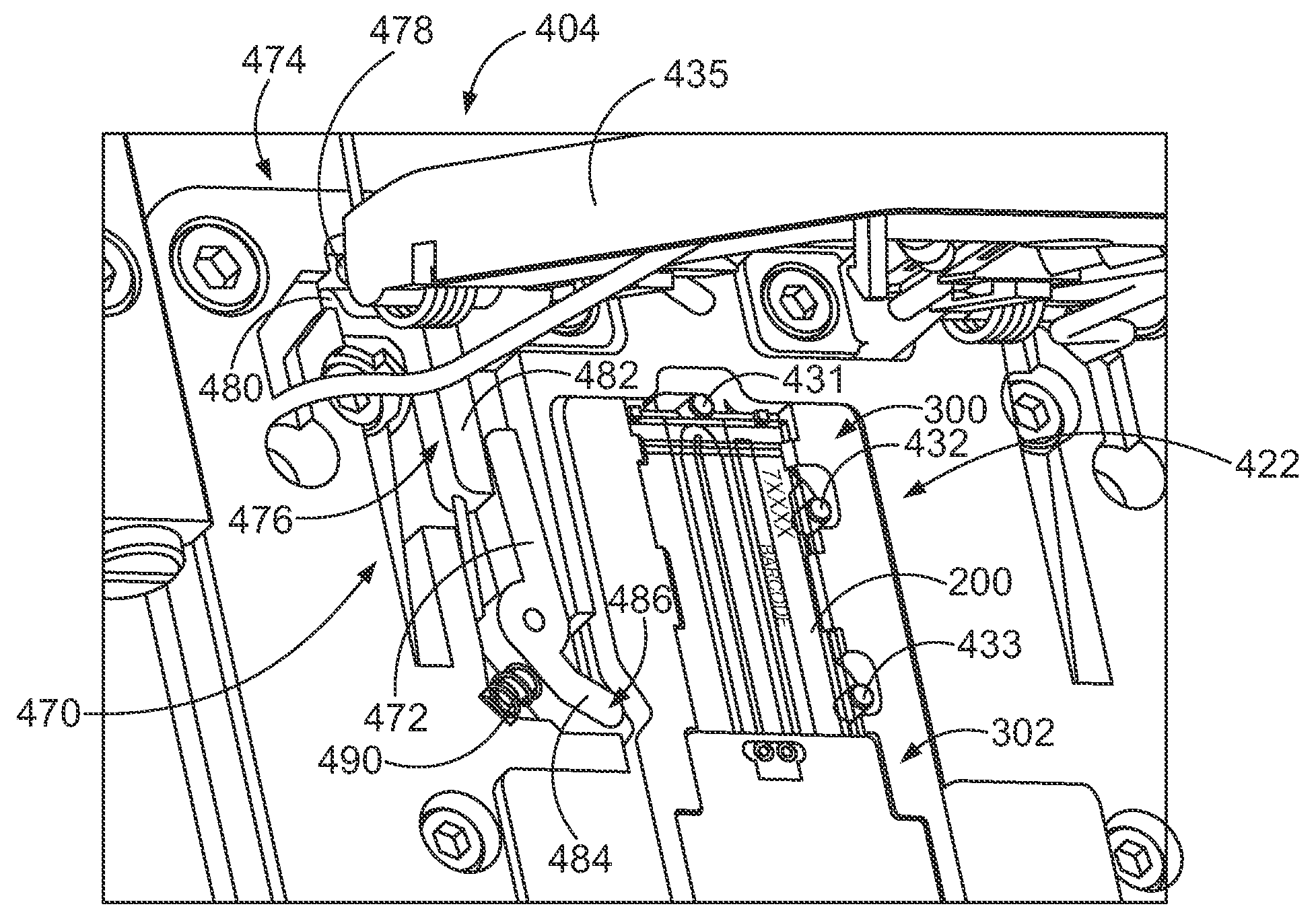
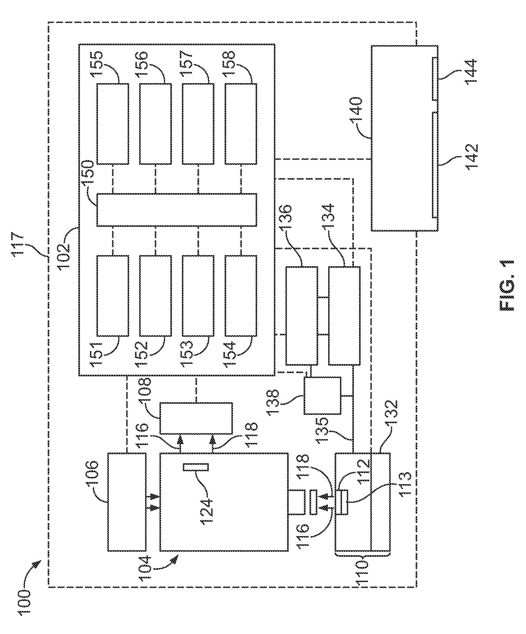
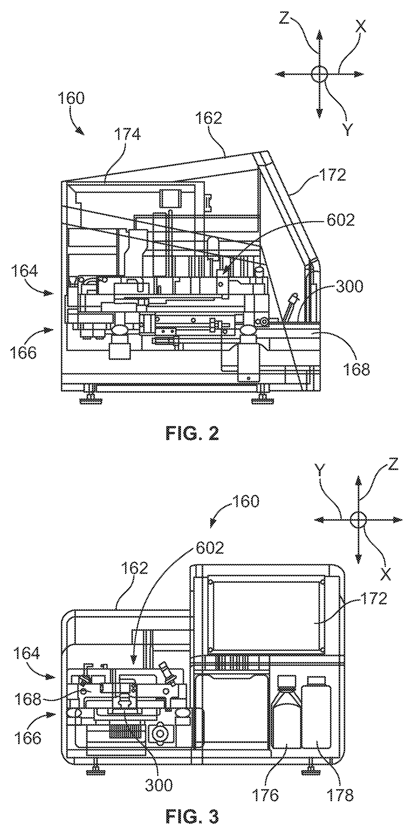
[0084]Embodiments described herein include various systems, methods, assemblies, and apparatuses used to detect desired reactions in a sample for biological or chemical analysis. In some embodiments, the desired reactions provide optical signals that are detected by an optical assembly. The optical signals may be light emissions from labels or may be transmission light that has been reflected or refracted by the sample. For example, embodiments may be used to perform or facilitate performing a sequencing protocol in which sstDNA is sequenced in a flow cell. In particular embodiments, the embodiments described herein can also perform an amplification protocol to generate a sample-of-interest for sequencing.

[0085]As used herein, a “desired reaction” includes a change in at least one of a chemical, electrical, physical, and optical property or quality of a substance that is in response to a stimulus. For example, the desired reaction may be a chemical transformation, chemical change, o...


PUM

PropertyMeasurementUnit
areaaaaaaaaaaa
length L1aaaaaaaaaa
length L1aaaaaaaaaa

Abstract

A fluidic device holder configured to orient a fluidic device. The device holder includes a support structure configured to receive a fluidic device. The support structure includes a base surface that faces in a direction along the Z-axis and is configured to have the fluidic device positioned thereon. The device holder also includes a plurality of reference surfaces facing in respective directions along an XY-plane. The device holder also includes an alignment assembly having an actuator and a movable locator arm that is operatively coupled to the actuator. The locator arm has an engagement end. The actuator moves the locator arm between retracted and biased positions to move the engagement end away from and toward the reference surfaces. The locator arm is configured to hold the fluidic device against the reference surfaces when the locator arm is in the biased position.

Description

CROSS REFERENCE TO RELATED APPLICATIONS[0001]The present application relates to and claims the benefit of U.S. Provisional Application Ser. Nos. 61 / 431,425, filed on Jan. 10, 2011; 61 / 431,429, filed on Jan. 10, 2011; 61 / 431,439, filed on Jan. 11, 2011; 61 / 431,440, filed on Jan. 11, 2011; 61 / 438,486, filed on Feb. 1, 2011; 61 / 438,567, filed on Feb. 1, 2011; 61 / 438,530, filed on Feb. 1, 2011. Each of the above applications is herein incorporated by reference in its entirety.BACKGROUND OF THE INVENTION[0002]Embodiments of the present invention relate generally to biological or chemical analysis and more particularly, to assay systems having fluidic devices, optical assemblies, and / or other apparatuses that may be used in detecting desired reactions in a sample.[0003]Various assay protocols used for biological or chemical research are concerned with performing a large number of controlled reactions. In some cases, the controlled reactions are performed on support surfaces. The desired r...

Claims


Application Information

Patent Timeline
Patent Type & Authority Patents(United States)
IPC IPC(8): C12M3/00B01L3/00B01L9/00
CPCB01L9/527B01L3/502715B01L2200/025B01L2200/027B01L2200/0689B01L2300/043B01L2300/0816B01L2300/0877B01L2200/04Y10T436/25B01L2300/022G01N35/1065G01N35/1011G01N35/1002G01N35/1079G01N2035/00435G01N35/08B01L7/52B01L3/50273B01L2300/041G01N21/05G01N2021/058
Inventor REED, MARK T.WILLIAMSON, ERICCRANE, BRYANLEUNG, PATRICKBUERMANN, DALEKINDWALL, ALEXANDER P.ERIE, FREDERICKPRATT, MARKHARRIS, JASONCARSON, ANDREW JAMESHONG, STANLEY S.BRYANT, JASONWANG, MARKVERKADE, DREW
Owner ILLUMINA INC
Learn More