Electrode inspection apparatus for spot welding

a technology for inspection apparatuses and electrodes, which is applied in the direction of electrode maintenance, television systems, instruments, etc., can solve the problems of deterioration of the tip condition and inability to ensure the quality of welded parts, and achieve accurate measurement, reduce availability ratio, and accurate performance

Active Publication Date: 2015-02-10
KEYLEX CORP
View PDF20 Cites 64 Cited by
  • Summary
  • Abstract
  • Description
  • Claims
  • Application Information

AI Technical Summary

Benefits of technology

[0022]According to the first aspect of the present invention, a distance from the electrode to the camera through the mirror is constant, and therefore, variations of the measured values are less likely to occur. Besides, the image of the tip of the electrode can be captured by the camera from the direct front thereof, and therefore, the captured image is processed by the calculation section, thereby measuring at least two or more tip diameters at one time. With this process, the measurement of the diameters of the electrode tip, i.e., determination of whether the tip has a true circular shape or not, is accurately performed without reducing availability ratio in a production line.
[0023]According to the second aspect of the present invention, both surfaces of the mirror reflect the respective tips of the electrodes at the same time, whereby images of the tips of the pair of the electrodes are captured simultaneously, and the diameters of the electrode tip is accurately measured without reducing availability ratio in the production line. Since the camera is not disposed between the pair of the tips of the electrodes, and only the mirror is disposed between the electrodes, a width of a portion of the inspection apparatus body located between the electrodes is short, thereby providing a compact structure as a whole.
[0024]According to the third aspect of the present invention, if the mirror rotates rotate 90 degrees, whereby each of tips of the electrodes is imaged by the camera. Therefore, the inspection apparatus is provided with low cost and a compact structure.
[0025]According to the fourth aspect of the present invention, the respective tips of the pair of the electrodes are simultaneously imaged by the camera even if the mirror does not rotate. Therefore, the inspection apparatus is provided with low cost and a compact structure without reducing availability ratio in the production line.
[0026]According to the fifth aspect of the present invention, the inspection apparatus has a compact structure while light that is necessary to capture images by the camera is sufficiently generated.
[0027]According to the sixth aspect of the present invention, part of the light emitted from the illumination light sources are shielded by the light quantity adjustment wall, thereby making it possible to set light quantity which is sufficiently for imaging the electrodes and to image the electrodes clearly.
[0028]According to the seventh aspect of the present invention, the protective cover prevents dust and the like attached to the tips of the electrodes from entering the inside of the inspection apparatus body from the fixing hole. The light emitted from the illumination light sources and reflecting on the protective cover is diffused in the curved portion of the protective cover, and does not reflect on the lens of the camera, thereby making it possible to image the electrodes clearly.
[0029]According to the eighth aspect of the present invention, even when the distance between the illumination light sources and the electrodes is shortened, the light emitted from the illumination light sources does not directly illuminate the tip of the electrode, and the structure avoids a state where the light directly illuminating the tip of the electrode from the illumination light sources reflects on the camera, and the like. Therefore, the inspection apparatus body has a compact structure while the electrodes are clearly viewed.
[0030]According to the ninth aspect of the present invention, the tip periphery of the electrode is clearly imaged on the image captured by the camera. Therefore, the calculation of the captured images by the calculation section is precisely processed, thereby making it possible to measure the diameters of the tips of the electrodes.
[0031]According to the tenth aspect of the present invention, unlike an LED of white light, when the blue LED is used, the blur in the tip periphery of the electrode due to glaze of the electrode does not occur, and the tip periphery of the electrode is clearly imaged on the image captured by the camera, thereby the calculation processing by the calculation section is further accurate.
[0032]According to the eleventh aspect of the present invention, the captured images or the processed data can be confirmed after the inspection. Therefore, a dressing cycle of the electrode and the like can be considered later based on the obtained data.
[0033]According to the twelfth aspect of the present invention, the workers can know the condition of the electrodes even if the workers do not enter the production line, and the workers safely manages the production line.

Problems solved by technology

However, after the welding is done a predetermined times, the tips of the electrodes do not have the true circular shape due to wear, or oxide coatings and the like are attached to the tips, resulting in deterioration of the tip condition, and if the welding is continuously performed with the tips deteriorated, the quality of the welded parts is not ensured.

Method used


Image

  • Electrode inspection apparatus for spot welding
  • Electrode inspection apparatus for spot welding
  • Electrode inspection apparatus for spot welding

Examples


first embodiment

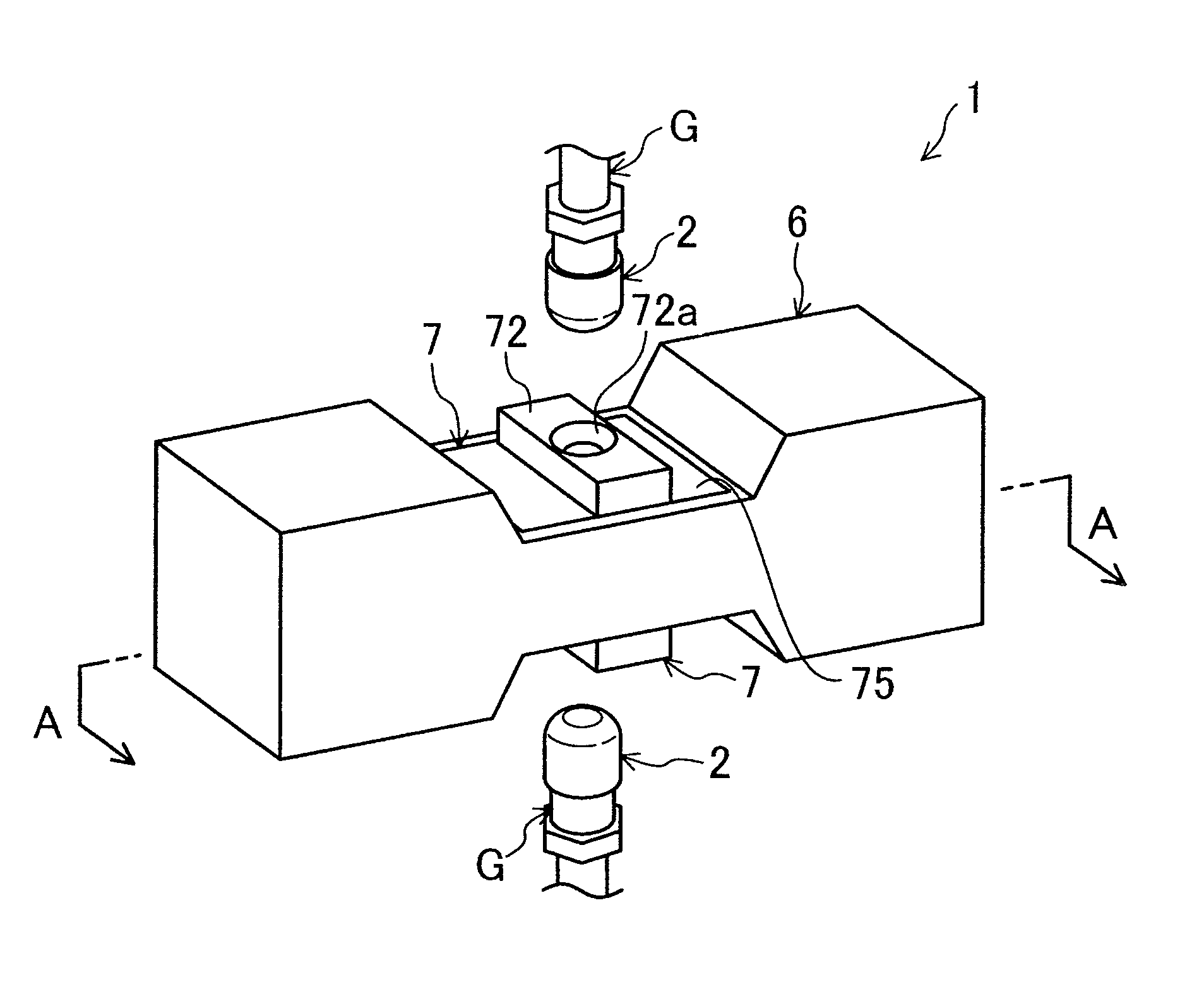
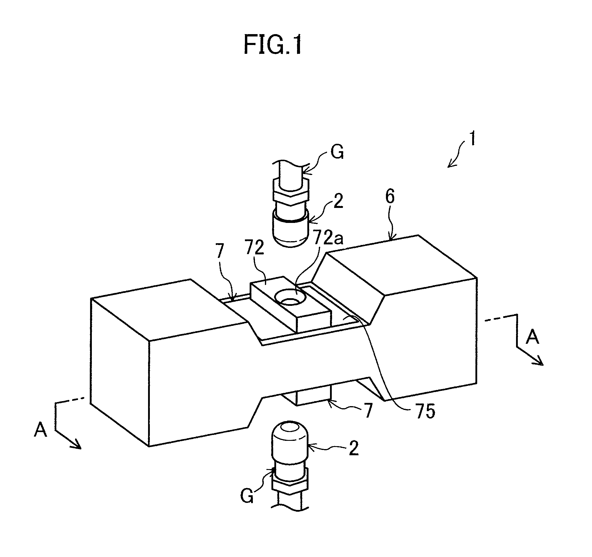
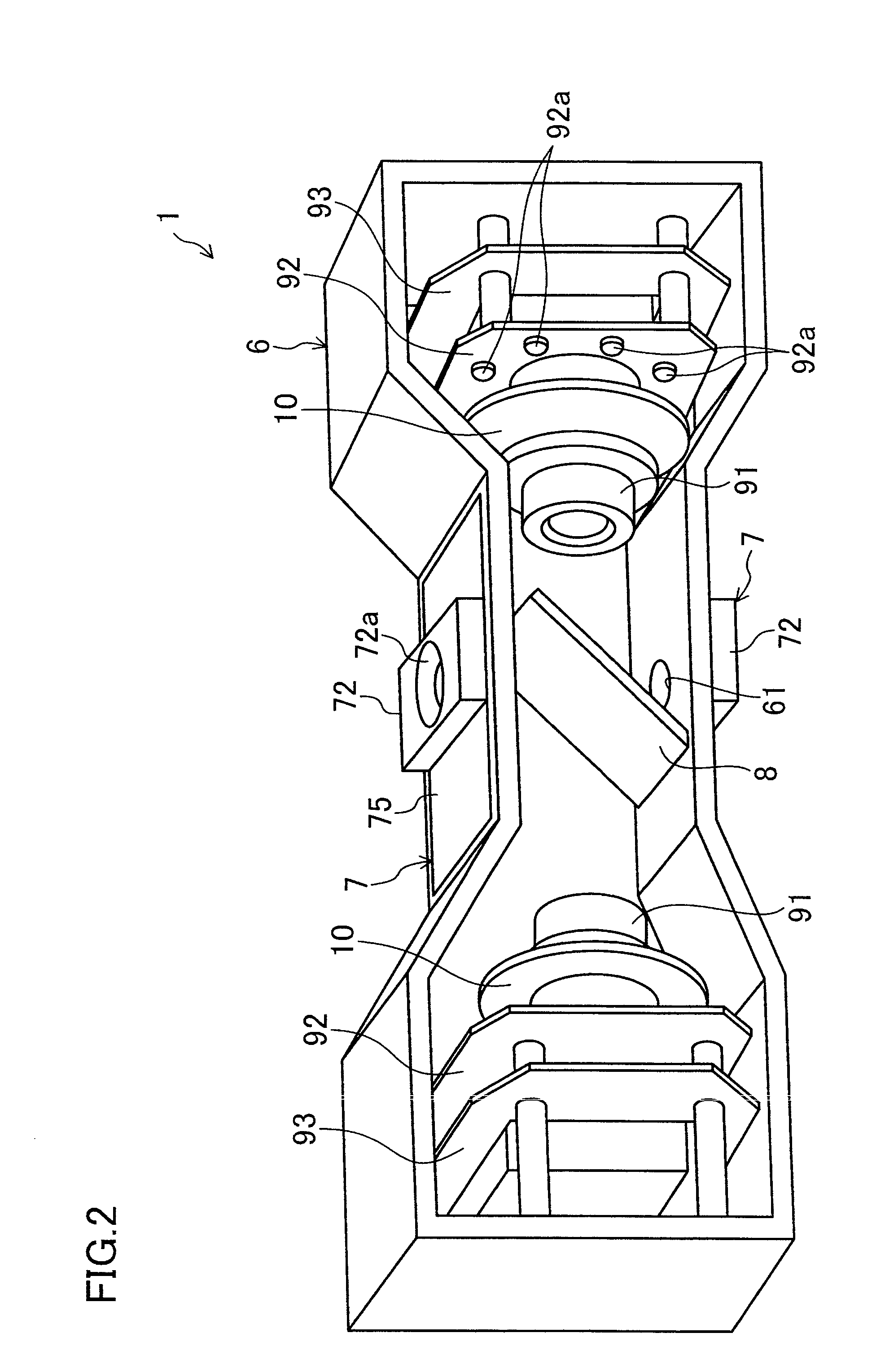
[0054]FIGS. 1-5 show an electrode inspection apparatus 1 for spot welding according to a This electrode inspection apparatus 1 is used for inspecting conditions of a pair of electrodes 2 made of chromium-copper or the like and mounted on and held to tips of a weld gun G used when steel plates are welded together by spot welding in automobile production lines. The electrode inspection apparatus 1 includes an inspection apparatus body 6 formed by processing steel plates.

[0055]The inspection apparatus body 6 is formed into a box shape of a substantially rectangular parallelepiped extending in a horizontal direction. Central portions of both upper and lower walls in the longitudinal direction are recessed, the distance between the central portions in the longitudinal direction are narrower than the distance between portions at both sides in the longitudinal direction. The outer shape of the inspection apparatus body 6 is vertically symmetrical. Each of the recessed central portions of ...

fifth embodiment

[0096]As shown in FIG. 14, the electrode inspection apparatus 1 for spot welding is formed in a flattened box shape with a thin thickness, and includes an inspection apparatus body 60, one side of the an inspection apparatus body 60 in the longitudinal direction thereof being curved outwardly so as to be formed into a substantially semidisc-shaped plate.

[0097]As shown in FIGS. 15 and 16, a mirror module 3 is disposed in the inside of the curved portion having a substantially semidisc-shaped plate in the one side of the inspection apparatus body 60 in the longitudinal direction thereof, a control substrate 50 is disposed in the inside of the other side, and a pair of electrode fixing plates (measuring reference units) 72 each having substantially a discoid shape and each including a fixing hole 72a for fixing electrodes 2 therein are disposed over and under the mirror module 3 so as to sandwich the mirror module 3.

[0098]The mirror module 3 extends in the width direction of the inspe...


PUM

PropertyMeasurementUnit
diameteraaaaaaaaaa
diameter r2aaaaaaaaaa

Abstract

An electrode inspection apparatus for spot welding is provided for precisely measuring diameters of a tip of an electrode without reducing availability ratio in a production line, and is particularly useful when inspecting a weld gun having electrodes with a narrow distance therebetween.A CCD camera 91 for imaging the tip of the electrode held to the weld gun is disposed in an inspection apparatus body 6. The inspection apparatus body 6 includes a measuring reference unit 7 in which a fixing hole 72a for fixing the tip of the electrode is formed, and a mirror 8 obliquely arranged with respect to the electrode so as to be distant from the fixing hole 72a at a position opposite to the electrode with respect to the measuring reference unit 7. The CCD camera 91 is disposed in a side of the mirror 8 with a distance therebetween for imaging the tip of the electrode from a direct front thereof reflected on the mirror 8 by reflection.

Description

TECHNICAL FIELD[0001]The present disclosure relates to electrode inspection apparatuses for spot welding used in, for example, automobile production lines.BACKGROUND ART[0002]Conventionally, spot welding techniques of pressing electrodes mounted on and held to tips of a weld gun to steel plates, applying a pressure thereto, and causing energization to provide resistance heating to the steel plates to weld them together have been used in automobile production lines. The spot welding techniques ensure reliability of products with proper management of current values during welding, weld times, applied pressure force, and conditions of tips of the electrodes. Among these elements, the tips of the electrodes ensure welding quality most stably if they have a true circular shape and do not include waste materials attached thereto. However, after the welding is done a predetermined times, the tips of the electrodes do not have the true circular shape due to wear, or oxide coatings and the l...

Claims


Application Information

Patent Timeline
Patent Type & Authority Patents(United States)
IPC IPC(8): H04N9/47H04N7/18B23K11/30G01B11/08
CPCG01B11/08B23K11/3063B23K11/30B23K11/36
Inventor YAMANE, TOSHIMASAYAMANE, YOSHIAKI
Owner KEYLEX CORP
Why Eureka
Try Eureka